Last modified: 2026-10-31 18:51:27
< 2026-10-30 2026-11-01 >I wired up the power button, not the alarm yet because I'm still not sure exactly how to do it.
Also messed about with getting the relay to work. Errors included:
But now seems satisfactory.
I do want to add a torch status LED to the front of the panel, and possibly a manual torch disable switch, just because I would be quite annoyed if the plasma arc lit unexpectedly.
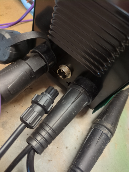
The torch trigger connector is GX16:
I tested it and confirmed that it is just a straightforward switch, squeezing the trigger shorts the pins together.
I am ordering a 2-pin GX16 connector. I could make do with the one I already have but would rather spend the £6.89 to get a second connector than hack up the existing one.
That brings total expenditure up to £94.54. Now dangerously close to triple figures.
So still to do:
Torch LED and switch done:
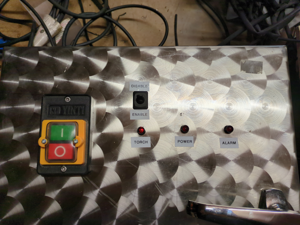
The light tells you whether FluidNC is trying to switch the relay on, and the manual switch also needs to be set to "enable" for it to actually switch on.
Also while I was messing around with it the X axis belt pulled out of one of the grippers, so I may need to redesign the X belt grippers as well, belts are such a hassle.
I'm going to try out Solidcraft some more in making these parts.
I think for the Y axis belt gripper I can just put teeth on it and should be fine. for the X axis one it probably wants something to actually clamp the belt instead of just sliding it in between the teeth.
OK, new Y belt gripper made (see below) and installed, seems good, but I'm not inclined to test it on purpose.
I've also figured out how to wire up the alarm light. I've set up the A0 pin on the Arduino as the alarm input and A2 as an alarm output.
So the ALM+ and ALM- pins on the HBS507 servo drives are short together in normal operation and open circuit when there's a fault. So FluidNC is configured with A0 set to active-low and a pull-up resistor. And we connect ALM+ to A0 and ALM- to GND. So when ALM+ and ALM- are shorted together (no fault) the A0 pin is short to ground. If the servo drive reports a fault, or (importantly!) if a wire gets broken, then the A0 pin is no longer short to ground and the pull-up resistor pulls it up and FluidNC recognises the fault.
And then, separately, FluidNC drives pin A2 high which lights the LED.
Good.
Still to do now:
Can I import a FreeCAD part in Solidcraft just to use as a reference?
It does have a FCStd import but it has imported it wrong. What about STEP import?
Yes, STEP seems to have worked. Can I make this one kind of transparent so that I can just use it as a reference while modelling one from scratch in Solidcraft? Yep.
The Solidcraft UI needs a lot of clicking-and-dragging, I wonder if I can have something like the FreeCAD "Touchpad" controls? Yes! Literally has an input scheme named "Touchpad", great.
My STEP file is not at the origin, how do I move it there? In FreeCAD I'd right click it in the tree and use "Transform" but that is not there in Solidcraft.
Ah, there is a "body" underneath the "component", and the body has a "Move/Copy" option.
Bug: during the move/copy the navigation scheme has reverted to default instead of sticking to "Touchpad". Also my semi-transparent part becomes opaque again during move/copy which means I can't see through it any more to align it properly.
https://github.com/tangency-labs/solidcraft/issues/10231
OK, I have it on the origin, let's make a copy of it from scratch but try to add belt teeth to it.
I made a "new component" to make my own one.
When I was drawing the outline of the part, with reference to the existing one, it snapped my line endpoints to the existing ones and seems to have auto-constrained them there. I can see why this would be useful but in this case it's not necessarily what I wanted because I wanted the experience of using the constraint tools. Oh well.
Weirdly my new component seems to be underneath the existing component in the tree instead of alongside it. Can components be nested? I dragged it up and seems to be fixed now.
When you click a face and go "new sketch" it seems to bring the existing shape of that face into your sketch, which is rarely what you want, I wonder why it does that.
When you want to make a pocket you need to do an "extrude" and change it to "cut" and change the direction to "reverse". You'd think the direction would automatically reverse when changing to "cut".
The FreeCAD window titlebar puts the name of the document first so you can see it in the window toolbar but SolidCraft window title is always just "SolidCraft"
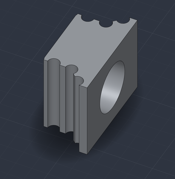
Not really great but may be an improvement on the previous version.
If I can't get these belt grippers to work properly then I'll probably need to buy longer pieces of belt and do something better. I think my main problem is I was trying to grip on a really short piece of belt so that I get the most range of travel.
< 2026-10-30 2026-11-01 >