
I have connected an electronic pressure sensor near the inlet of my Wig-Wag so that I can test the hypothesis that the actual pressure available at the inlet changes throughout the cycle of the engine.
The idea is that the hose restricts the flow of air. So when the engine's inlet port opens, the air at the end of the hose drains into the cylinder, and it takes time for the hose to fill back up again.
Pressure sensor
My setup looks something like this:
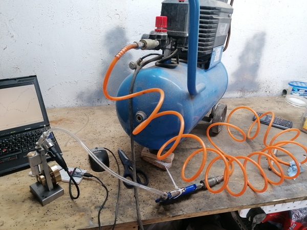
In that picture, the laptop is running the Arduino IDE's "Serial Plotter", there is an Arduino Nano on the breadboard running the "AnalogReadSerial" example program, there is a pressure sensor connected to an analogue input of the Arduino, and screwed into an aluminium fitting that I made, and the aluminium fitting is inline with the air supply hose.
This picture better shows the connection of the sensor to the air hose:
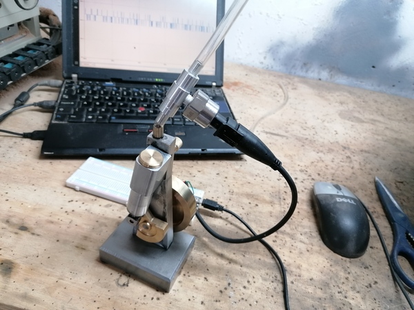
I got the sensor from eBay for about £15 (search "pressure transducer"). It takes a 5 volt supply and gives an analogue output between 0.5v and 4.5v, supposedly linear in its range of measurement. Mine has a 30psi range (= 200 kPa), but there are others with different ranges.
First measurements
Here's a video of the system in use:
You can clearly see that the measured pressure is not constant, and does indeed vary throughout the engine's cycle. The simulator does not simulate this, it assumes that the inlet pressure is constant. The simulator acts as if the inlet port is connected to a high-pressure "second atmosphere".
There are a few points in the video where the plotted pressure goes up and the engine slows down: this is because I was pressing my finger against the flywheel to add some load to the engine. It's not obvious to me whether the measured pressure increase is primarily because the engine is running more slowly (so there is more time for the hose to "fill up" with air when the port is closed), or because the engine is providing more resistance (so the hose doesn't drain as quickly when the port is open). Maybe both.
The pressure measurement has two obvious peaks throughout the cycle, and the smaller one gets larger as the load increases:
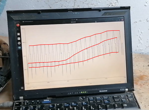
From playing around, it seems like it stalls at the point where the small peak meets the large peak. Not sure if that means anything interesting.
The long hose
To test the hypothesis that the long hose is causing the restriction, I can remove it and connect the air gun directly to the compressor:
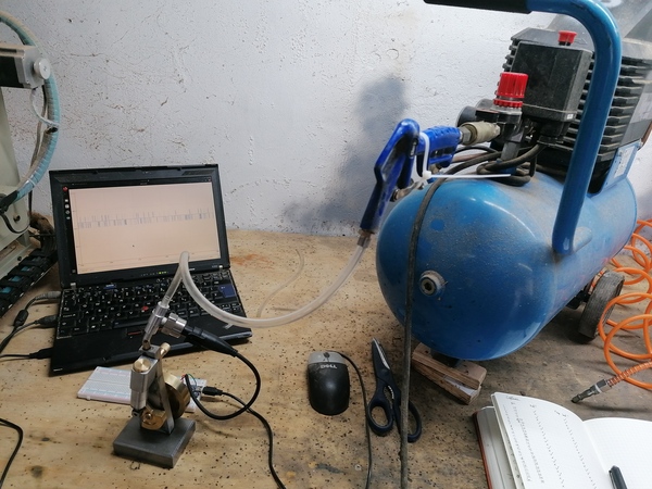
If the long hose is the restriction, then when the hose is connected we'd expect the measured pressure to be lower and to fluctuate more.
I captured pressure data from several runs at three different pressures, both with and without the long red hose.
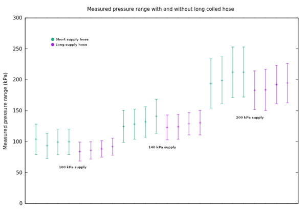
The "error bars" are showing the range between the minimum and maximum recorded pressure from the sensor, over a period of 5 seconds in each case.
We can see that with the long hose connected, the average pressure is lower as we expected, but also the magnitude of the fluctuation is lower. So I think that while the long hose does increase flow restriction overall, it also acts a bit like a second air tank, allowing more air to flow for short periods without changing the pressure as much, because it can drain out of the hose without having to come through the valve on the main tank.
It may also be notable that the maximum recorded pressure appears to exceed the supply pressure in each case. I am not yet sure whether this is because of the engine pushing air back into the hose, or just a result of mis-calibration of either the electronic sensor or the gauge on the compressor.
Conclusion
For a more accurate simulation: instead of exposing the inlet port directly to the "second atmosphere", the inlet port could be exposed to a reservoir (representing the hose) that is itself connected to the second atmosphere through a small orifice. We'd then use the selected air flow method to calculate both the flow from the reservoir to the port, and the flow from the supply pressure into the reservoir. I'd also like to add an "oscilloscope" to the simulator so that you can get it to plot things like the pressure in the reservoir over time, to see how it compares to the real-life data.
For a better-running engine: maybe add a large air reservoir near the inlet port? It should make the engine run faster on any given supply pressure because the pressure won't drop as far when the port is open. It might be interesting to try this with a valve on the entrance to the reservoir, so that it can be "turned off" while the engine is running, to more clearly see what effect it has.
I've also observed that the engine seems to be running in nicely. Last time it wouldn't run below about 10 psi, but today I've noticed that it will run even at pressures low enough that the gauge reads 0.
Electricity analogy
I'm kind of getting into analogue electronics at the moment, and it's surprising how many ideas can carry over.
We can think of pressure as voltage and flow rate as current.
Restrictions to flow rate are the same as resistance. Reservoirs for air are a bit like capacitors (e.g. with one leg attached to ground: they can store up pressure and release it later).
The engine presents an inductive load, just like an electric motor, because of the inertia of the flywheel (it wants to keep pulling air through even once the supply is switched off).
The supply hose acts like a wire with high resistance, and combined with the resistance presented by the motor, at any given point in its cycle, they form a voltage divider, which we are measuring with the pressure sensor (i.e. voltmeter).
So then the issue with the pressure dropping when the port opens is just like brownout when a circuit increases its current draw. The solution to brownout in electronics is to put a bypass capacitor near the power input to the affected device, and the solution I have proposed for the engine is exactly the same: putting a "reservoir" near the inlet to the engine is the same as adding a bypass capacitor.
For a better analogy to a capacitor, we'd probably want to make the reservoir out of a balloon. That way it is actually acting against the atmosphere (i.e. ground potential) instead of just getting pressurised on its own. What we've got with a reservoir is basically like a capacitor that only has one terminal. Like a big metal plate hanging off a wire. I'm not actually sure why a capacitor works more than twice as well as a single metal plate does. I should find out.