Last modified: 2025-11-10 22:10:38
< 2025-11-09 2025-11-11 >This example https://www.youtube.com/watch?v=CM92JnbMg8o has the moon acting like a cam follower type thing, on a track that is tilted and rotates, so that it can incline the moon orbit differently at different times.
Also, I had an idea for keeping the lit side of the moon pointing towards the sun! You need a forked rod coming off the moon, and the fork needs to hold the rod that the sun is on. That way the forked rod always points towards the sun, so if the moon pivots with the forked rod then it will always face the sun.
You can make sure it doesn't interfere with the motors/house/earth by making the forked rod mechanism stick out the bottom.
Maybe make it a telescoping rod instead of a forked rod, if you don't want the loose end of the fork sticking out a long way when the two objects are close together. Or make it a spring.
Let's say the moon orbits inside the sun, and the sun's orbit has a diameter of 400mm, and the moon orbit is 30mm closer in. Whatever mechanism ties them together has to be able to span distances from 30mm up to 370mm.
Maybe a very fine spring made of many coils of very thin wire?
A telescoping rod won't work because you can't fit 370mm worth of telescoping into 30mm unless you have 13 segments, which is absurd.
A forked rod would work but when the two are close together it would stick out by 340mm which is bad.
ChatGPT suggested using those retractable string line mechanisms! Genius! Like you get on lanyard strings or whatever. So it naturally coils up and holds the string on the moon, and you can stretch it out to the sun however far it is.
You can put a reel at both ends and tie the strings together in the middle so each reel only needs to range from 15mm to 170mm.
It is apparently possible to do it with differential gears, but I actually prefer the simplicity of the string line idea.
ChatGPT suggests buying lanyard reels and taking them apart to get the springs, and then mounting the springs in my own custom housing as part of the orrery, and using fishing line for the string. I might not even need to use 2 of them, the first one I looked at on Amazon says it can extend up to 68cm which is way more than I need.
Potentially you could have a full moon model that always faces towards the Earth (so doesn't need any special mechanism, just fixed orientation relative to its drive motor), and then a black hemisphere around it that is always pulled to face away from the sun, to hide the parts of the moon that are not lit. That way you get the effect of having the same side always face towards Earth, while also getting some of it obscured when it is not lit. In fact you could have the part that faces away from Earth painted black as well, so that you can easily see the moon phase. Maybe this is just overcomplicating it. A black-and-white ball that has white side facing sun is probably fine.
I have some 12mm plywood, 1.2m by 0.6m, to make the bonnet out of.
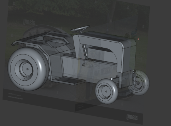
I was umming and ahhing about how to make the bonnet for ages, because I wanted to be kind of faithful to the TE20 shape, which has a lot of complicated curves.
But discretion being the better part of valour, I have decided to keep it simple.
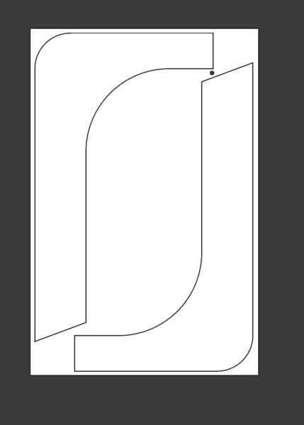
The two side pieces will be cut out on the CNC machine as flat plates, with just a single curved surface at the front top edge. And small roundovers on each side with a 12mm roundover bit in the handheld router.
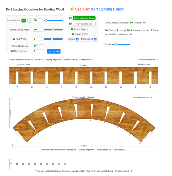
The only question was how to make the curved surface at the front top edge. Initially I was going to 3d print it, but Ruari suggested I could make it by doing the thing where you cut lots of grooves into the wood to allow it to bend. I thought this sounded great. So the plan is to cut out the left and right sides with the CNC router, and then cut a long rectangle to form the top/front, and cut grooves into it to form the bend. I may have to experiment with a smaller piece to work out the depth and spacing of the grooves to best form the bend, but I think this will work. And if it doesn't I can revert to 3d printing.
So I don't see any reason I can't do the CAM for the left/right side panels now and cut them out quite soon.
Looks like they will both fit on the machine in a single job:
There is https://www.blocklayer.com/kerf-spacing for kerf bending calculations.