jes notes Index Gallery . Clavichords Cyclecar Dehumidifier Financial Data FreeCAD MSVA Philosophy Signed Distance Functions Shaft passers Snap issues
2024-12-30
Last modified: 2025-01-01 09:55:26
< 2024-12-26 2025-01-01 >
Clock frame
Finally, Christmas is over and screws have arrived. I have the M5x10 black allen screws
from Boltbase, which look how I wanted but 10mm is slightly too long :(. And I also
have M5x8 stainless ones, but they have pozidrive heads instead of hex sockets! What
a blunder.
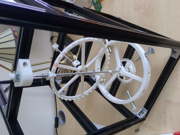
I don't care though, onwards, I'll use these stainless ones. The plan is to build
up the existing mechanism on the aluminium extrusion frame, and let it run for 4 hours and
see how it goes.
Not exactly sure where to start, I guess start building up 2 side pieces and then join
them.
First impression: wow, this is a really time-consuming way of building things.
Issues are:
- it's really hard to get the screws properly done up on an inside corner (partly this is a pozidrive problem)
- sometimes the T-nuts don't rotate and wedge inside the extrusion, they just come out
- if you undo the screw a bit to get it out, you might drop the T-nut off the end and then it falls down the tube
- seems like the brackets will very easily shake loose because it's so difficult to get the screws properly tight
- getting the brackets properly in the corner is difficult because you have to tighten it up one piece first, and then there's no decent reference for getting it square to the end
- trying to tighten the screws properly is rubbing the skin on my palm (this is a pozidrive problem)
- if you prepare a short piece with an angle bracket at each end, you then can't fit it in because the angle bracket has protrusions that poke into the extrusion
Some progress:
Things I still need to solve are:
- how am I going to do the escape wheel shaft bearings? there's not an awful lot of room when the remontoire is behind it
- need to make a part to hold the end of the balance spring
- modify the arm-catching surface to be at 90 deg. to the gear shaft if the remontoire adjacent shaft will be parallel
- mount the quadrature encoder
Escape wheel shaft bearings: make one single long-ish component that takes 2x micro bearings.
Balance spring holder: something that bolts to the underside of the beam that holds the
balance shaft upper bearing. (I admit that being able to bolt stuff to all 4 sides of
the extrusion is very convenient).
Arm-catching surface: straightforward.
Quadrature encoder: just needs a bracket to go on the upper side of the beam that
holds the balance shaft lower bearing.
I noticed that the bevel gear on the escape wheel shaft is quite wobbly. Even if I true it
up a bit, it gets pulled to one side when the grub screw is tightened. Maybe need something
better there.
I've ran out of time for now. Status is:
- escape wheel is in its "final" position with its "final" shaft
- balance wheel pivots are in place, balance wheel not installed
- balance spring clamp is printed but not tapped
- encoder bracket is printed but not tapped
- arm-catching block is printed but not reamed
OK, I made some more progress. Tapping and reaming done, balance spring holder installed,
encoder installed. So now I can swing the balance wheel with the escape wheel disconnected
and see it swing back and forth and plot it in the UI again. So I have my first plots from
the new frame! Good.
Next up is designing the bearing holder for the remontoire driving side.
The shaft for the remontoire driving side is quite damaged, I'll probably want to make
a new one.
Todo next:
- make a shorter pinion for the driving side of the remontoire
- make a bearing holder for the driving side of the remontoire (it wants to be like a U shape with one support on the beam and one the other side of the pinion)
- install the remontoire driving side
- install the remontoire adjacent shaft
- install the shaft with winding drum
- run the clock
< 2024-12-26 2025-01-01 >