Last modified: 2024-02-20 22:17:33
< 2024-02-19 2024-02-21 >Still needed:
In fact, after Z bearings and gantry supports, I can potentially do some FEA to work out where it is least rigid and improve it.
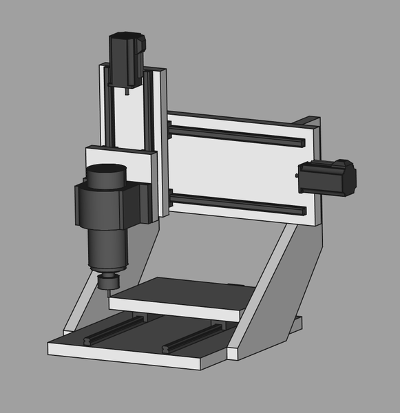
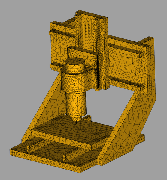
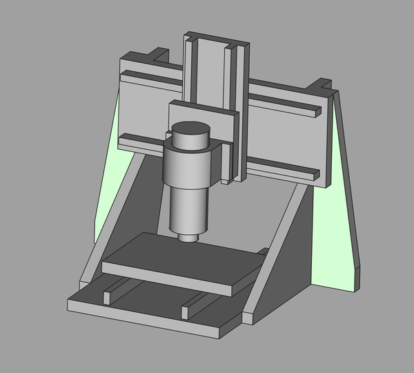
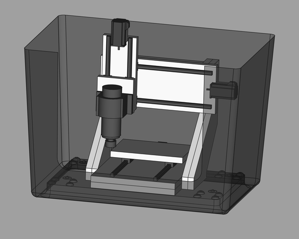
This is the design I want to test first:
I'm having some trouble getting Netgen to turn it into a mesh:
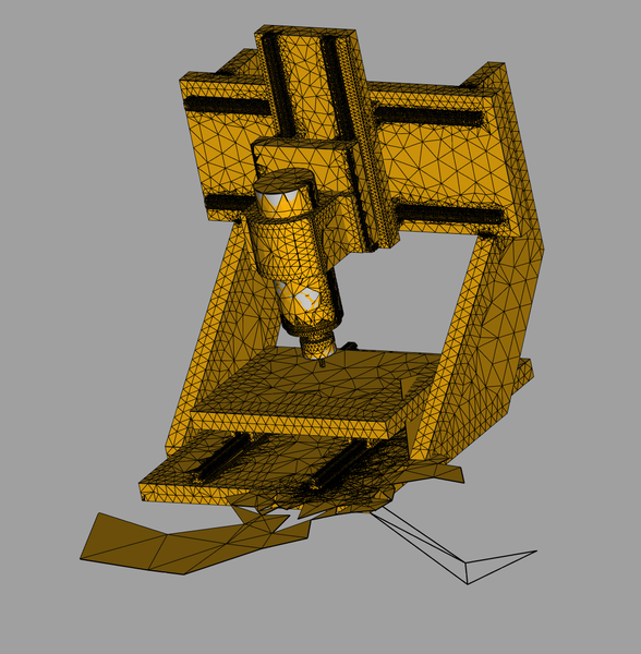
New plan: save the model as a STL, load the STL back in, use Part workbench to create shape from mesh with "sewing" enabled, and then use Netgen on that shape.
Great success!
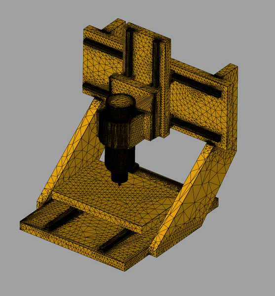
I'm not sure it's spending the triangle budget in the wisest way, but I'll take it.
Also, I now have an opinion on what is better out of putting the plates further apart and sinking the blocks into the plates. I think sinking the blocks in is better, because it reduces the size of the leverage on them, and you don't lose as much strength as it looks like, because there is still material in the area that was cut away, it's just bolted to a lower thickness. But as long as the bolted joint is sound, I don't think it substantially weakens it.
One simplification in the FEA is that the entire machine is made out of uniform "generic aluminium".
Another simplification is that we assume the linear bearings are rigidly attached to the rails. In reality the linear bearings are obviously free to slide, and the forces are reacted by the ballnut and ballscrew.
I'm modelling the forces by telling it that the table is fixed in space ("Constraint Fixed") and then applying a force of 100N to the flat surface at the bottom of the tool ("Constraint Force"), with the tip of the tool in the centre of the table and 25mm up in Z.
It is taking a very long time to do the calculations,
but I attached with strace and it does look like it's
making progress. It would be nice if it gave some sort
of progress indicator instead of just blocking the UI
thread until done.
Hmm, I don't know what it spent a very long time on, but it hasn't given me any results. I think I clicked the "Solver" button in the taskbar, but when I click it now it doesn't take a long time to compute anything, and tells me my FEM mesh has no volume elements.
It is writing a bunch of stuff into ./test.out. From
looking in the source, this is something to do with Netgen.
From https://incoherency.co.uk/blog/stories/freecad-fea.html it sounds like I used Gmsh instead of Netgen before, but I can't install it right now.
I ran a FreeCAD FEM example, and it worked fine, which suggests my problem is that the mesh has holes in it. I wonder if I can patch it up somehow.
The Mesh workbench has a "Fill holes" option, doesn't fix it though. I tried to "Remesh" in Blender and it crashed Blender.
I think the core issue is that I have multiple parts with coincident faces and nothing in the chain from "separate Part Design parts" to "single FEA mesh" is noticing that these need to join up.
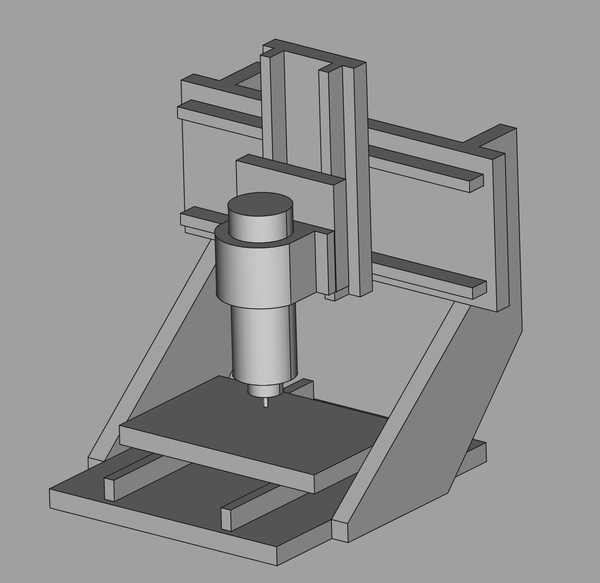
OK, new plan: model everything again, but this time as a single Part Design object, obviously simplify the rails etc., and then try to do FEA on that.
That was a lot less time than I've already wasted on mucking about with meshes.
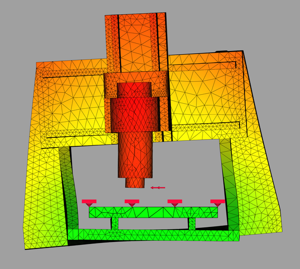
And Netgen generated a good mesh first time:
The first result was that almost all of the deflection occurs in the tool rather than the machine. However that is probably because I told it the tool is made out of aluminium. Since I can't easily make different parts of the model have different materials, I'm going to lose the tool and pretend all the force is at the collet nut, now 45mm above the table.
With a 100N load:
I didn't test X+ and X- separately because the machine is left/right symmetrical. And I didn't test Z- because you don't generate much force in Z-.
So this was worthwhile: I have discovered that the machine is most flexible in the X direction, which is not what I expected.
The easy fix is to add some perpendicular bracing pieces to the uprights. And probably to the gantry as well, but that probably wants testing separately.
But first I want to increase the load to 1000N:
OK. I've extended the existing uprights back a bit, and added some buttresses:
I think buttressing like this is going to be more effective, and use less material, than doubling up the thickness.
And now with a 1000N load in X, the displacement is reduced from 0.17mm to 0.10mm. Not actually a massive improvement.
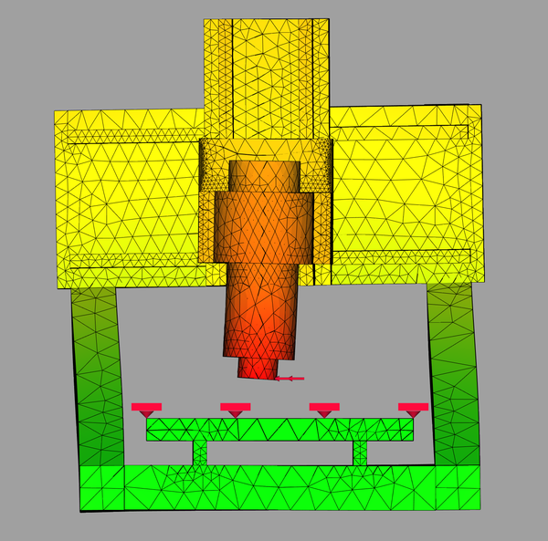
It flexes like this (500x exaggerated):
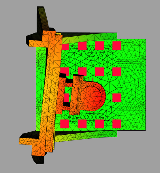
So it looks like most of the movement comes from flex in the base plate. I hadn't even thought of that. Even if I was going to double up on materials I don't think it would have occurred to me to double up the base plate. The base plate would be slightly stiffer in practice because it would be bolted to the steel stand.
Out of interest, if I simply doubled up the uprights, instead of adding buttresses, what would the displacement look like with a 1000N load along X?
Lol. Max. displacement is now 0.09mm. So this is in fact slightly better than buttressing. It still twists in the same way, mostly from the base plate flexing.
I'm going to try doubling up the base plate and gantry as well.
Now the max. displacement is 0.05mm and I think the majority of that comes from bending the spindle motor, and most of the rest from twisting the uprights.
Displacements with other loads are:
In Y+ the flex comes mostly from bending the spindle motor, also from bending the bottom of the gantry back, and bending the tops of the uprights back. And Y- is the same but directions reversed.
In Z+ the spindle motor doesn't appear to bend much (as you'd expect), but otherwise it's the same story: gantry and uprights bending.
So I say let's proceed with this design: forget the buttress pieces, double up the base plate, uprights, and gantry. The maximum displacement is reduced by more than 3x in X and more than 2x in Y and Z.
Next up I want to lay out the flat pieces of material that I have, and check that I actually have enough to make all these parts. My feeling is that I probably do, but need to check.
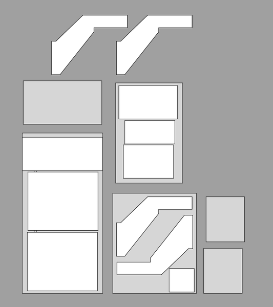
D'oh. I don't have enough material! If I use the damaged section of the big piece, then I can do everything except the second set of uprights, and still have 3 smaller pieces of material left over. The gantry piece is very close to the exact width of the big piece of material, but the gantry can be made slightly narrower with no downside, so I'm not worried about that.
Update:
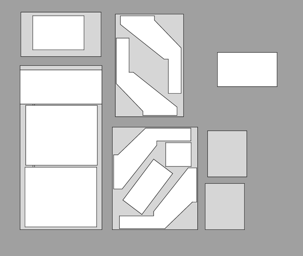
That gets us everything except the second piece of gantry. Since that is just a piece that gets bolted to the back of the gantry, could I tolerate making it out of 2 halves that are each bolted on separately? I think so. So then I make the secondary gantry piece in 2 parts, and I can get all of my parts out of the material I have:
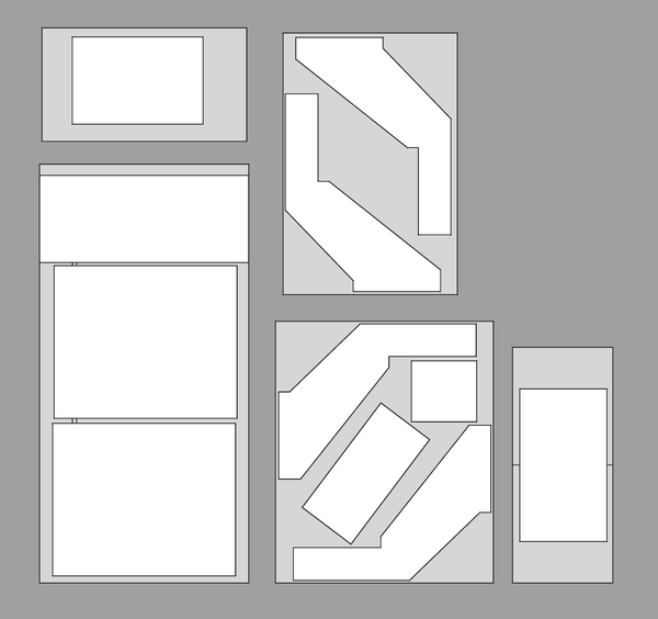
Great success.
The square/rectangle parts can be cut out by hand, but I will need to use the CNC router to make some of the others, which could prove problematic because they are too big to fit on the machine. Could use Ruari's machine?
Also I will probably want to mirror one of the parts with uprights on, because the material has one nice side and one rough side, and if I want everything symmetrical I will want 2 each way around.
OK, onwards:
Regarding ballscrews, I think the ballscrews I currently have are actually too long. Obviously I can cut them shorter, but can I turn a smooth section on the end to locate in the support bearing, or are they too hard? Can I even hold them in the lathe without damaging them?
Things I will want to check before actually making any parts:
I think for designing motor brackets and positioning screw holes I'll want to know those exact dimensions.
So maybe the next useful thing to do is dismantle the milling machine?
I tried scratching a piece of aluminium with a piece of kitchen worktop, and it looks like the worktop is softer than aluminium. That probably means the machine will perform worse than the FEA suggested.
< 2024-02-19 2024-02-21 >