Last modified: 2024-02-23 14:01:44
< 2024-02-20 2024-02-22 >I did the same tapping test as the other day, except this time with M12. The result was the same.
For M8, M10, or M12, drill with the largest drill that is less than or equal to the nominal drill size. For M12 I used a 10mm drill.
Then first tap with the smallest tap using the cordless.
Then tap with the middle-sized tap.
Then you can screw in a bolt. Tightening it up with the impact driver or a spanner won't strip the thread, but it will strip relatively easily with the long breaker bar.
So perhaps I want to be getting threaded inserts and epoxying them into the material, instead of tapping it directly? Or, where possible, bolt through it with a nut on the other side?
The composite kitchen worktop brand is "Minerva" https://www.minervaworksurfaces.co.uk/
I'm hoping to find out the density of the material so I can calculate the mass of my machine frame. If they don't tell us anywhere then I'll have to weigh a piece to find out. It would be good to find some sort of datasheet though, perhaps they also specify hardness and Young's modulus (ha).
Oh, the installation manual has advice about putting threads in it:
If any additional fixings are needed in the worksurface, you will need to drill a hole, and then use adhesive to secure a brass insert into the hole. You can then screw into the insert - Do not screw directly into the surface as this can cause the surface to split. We recommend an M6 regular length threaded insert, max length. 10mm. Packs of 8 available on our website.
So, yes, I want to be gluing threaded inserts into the material instead of cutting threads in it directly.
On cutting they say:
If you are cutting using a hand held skill/circular saw then cut face up. Cut edge should always be clean cut with the router.
I remember the circular saw chipped the edge quite a lot, so this is wise.
So from searching around it seems like Minerva is considered "acrylic". The density of acrylic is 1.18g/cm^3, but the density of the worktop will be higher depending on how much stone stuff is mixed with the acrylic.
Apparently they're only about one-third acrylic, the rest is ground up stone.
But let's assume 1.18g/cm^3 for now. What is the volume of the parts I have designed?
I can find out the volume of an object in FreeCAD using the Python console:
App.ActiveDocument.getObjectsByLabel("Base")[0].Shape.Volume
for an object called "Base". And since I have everything in a MachineFrame link group, if I delete
everything apart from the acrylic/composite parts, then I can take the volume of MachineFrame and that
is the total volume of worktop parts I will have, which comes to about 20800000 mm^3. That works out
to 20.8 litres, which would be about 25kg at the density of acrylic.
Honestly that is less than I was expecting. Disappointingly low. I was king od hoping it would be over 100kg.
Also, if I change the FEA material from "Aluminium-Generic" to "Acrylic-Glass-Generic", then the max. displacement in the 100kg Z+ load increases from 0.03mm to 0.87mm. Ouch, that is a lot worse.
Obviously the stone composite in the acrylic will make it heavier and stiffer, but I don't know by how much.
FreeCAD has the acrylic Young's modulus at 2.5 GPa, I read online that Corian Young's modulus is 9 GPa. Let's edit the acrylic material to bump it's Young's modulus up to 9 GPa. Aluminium is apparently 69 GPa, so a lot more.
Bumping it up to 9 GPa (and not changing anything else) shows the max. displacement is now 0.25mm. Still 10x worse than it would be if it were made of aluminium.
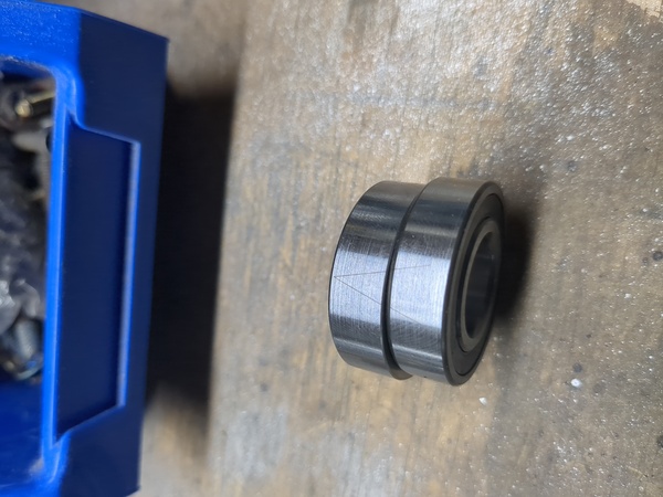
I've taken apart the 1.5kW spindle motor to see how easy it is to replace the bearings.
There are 2 bearings at the front, with a marking on the outer race to presumably show the intended direction and order of the 2?
And 1 bearing at the rear, which is marked with the "larger" of those 2 markings.
And all 3 are marked "KH6002-2RZ CTNT/P4 DT CAA S" on the outer race and "1912" on the inner race.
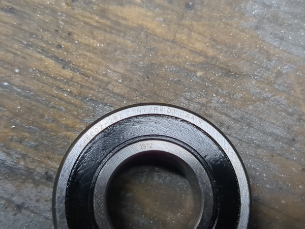
Also marked "OUSRC" on the outer race, 180 deg. away from the "KH6002..." marking.
The other side of the rear bearing is marked "-3" on both the inner and outer races. One of the others is marked -2 as well and the other is -2. Also, one of the others has the outer race ground down as well.
I found this drawing on https://www.cnc4you.co.uk/Spindle/Water-Cooled/Spindle-Motor-Single-phase-to-3-Phase-2.2KW-Water-cooled-ER20-with-Matching-VFD - might have been helpful:
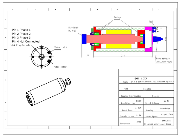
I'm not thrilled by "custom bearings". What bearings should I buy?
So the markings are confusing about whether it is "deep groove" or "angular contact". Apparently they are 2 different types.
I pulled the seals off one of these, and I think it is not angular contact. The cage is made of some sort of plastic, maybe PTFE type stuff. And it looks like the surface with "-3" written on it has been ground down, presumably this creates clearance between the 2 inner races so that they can be tensioned against each other.
I'm tempted to just buy some reasonably high quality bearings of the right size and use a shim washer to space the outer races apart, so that I can tension the inner races. I think the ones I took off are precisely ground so that when you do it all up fully tight you have the right amount of preload. Maybe I'll just have to preload it to taste and hope the Loctite holds it tight?
"SimplyBearings" have "super precision" angular contact spindle bearings in this size, but the cheapest is £60 +VAT, so it's a no on that.
They also have "budget" 7002 angular contact bearing for £11 +VAT, or lots of options for 6002 deep groove bearings.
So the question is: would I rather have "budget" angular contact bearings, or quality deep groove bearings? I shall email them and ask.
They tell me that "traditionally super precision spindle bearings are used", which I gathered. They also tell me that despite being numbered 6002 my bearings are in fact angular contact bearings.
Meh, I don't know what to do. I can't actually feel anything wrong with these bearings, but they don't seem to have a lot of grease inside. I think I'll just squeeze some more grease inside and put it back together, and if it proves to be a problem then I'll revisit at a later date. And when I reassemble, need to make sure that thrust is applied in the direction of the arrow marked on the outside of the outer race.
Well I put some more grease in the bearings (from the small tube that came with the Prusa Mini). And I've put most of it back together and done it up tight, but there is 1 or 2 mm of axial play and I'm not sure why. I think I need to take the top cap back off and see if the nut under there can go any tighter. Out of time for today though.
< 2024-02-20 2024-02-22 >