Last modified: 2024-02-23 14:01:44
< 2024-02-21 2024-02-23 >I think I would like to tinker with my design in FEA and see if I actually can get the machine deflection below 0.1mm for a 1000N load.
Also, I found a datasheet for Corian: https://casf.com.au/wp-content/uploads/2022/01/Performance_Properties_of_Corian.pdf
Presumably it's not exactly the same as Minerva, but it should be better than my made-up Acrylic derivative.
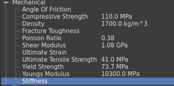
From the datasheet:
And thermal expansion is about 50% more than for aluminium, but I honestly don't think I'm yet at the level where I need to care about thermal expansion.
Given that we have 2 different moduli, which one do we put in "Young's modulus"? Wikipedia says:
Young's modulus (or Young modulus) is a mechanical property of solid materials that measures the tensile or compressive stiffness when the force is applied lengthwise. It is the modulus of elasticity for tension or axial compression.
So I guess the "tensile modulus"? But then what do I do with the flexural modulus?
Maybe "flexural modulus" is the same as "shear modulus"? Seems unlikely.
I've gone with:
And the new displacements, with 1000N load as before, are:
To be honest it looks like the vast majority of the deflection is in the spindle motor.
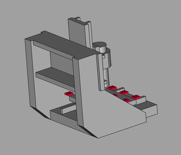
The first thing I want to change is making the uprights a bit longer in the machine's Y axis, because most of the triangle cut-out at the back is just wasted material, and since I moved the machine towards the front of the tub I now have more thickness for the narrowest part.
That gets us to:
So this is better.
Is Y+ always the same as Y-? Unclear whether it should be. I think I'll keep testing both just in case.
The next thing I want to try is putting a perpendicular stiffener along the back of the gantry. So that this doesn't need extra material, I'll just cut the gantry rear place in half and put one piece at the top and one at the bottom.
So now it looks like:
So a bit better still.
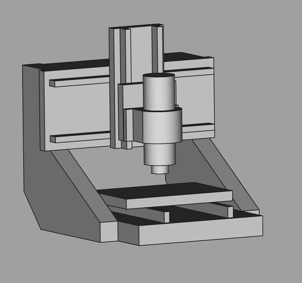
It's pretty obvious that most of the deflection is coming from the spindle motor itself:
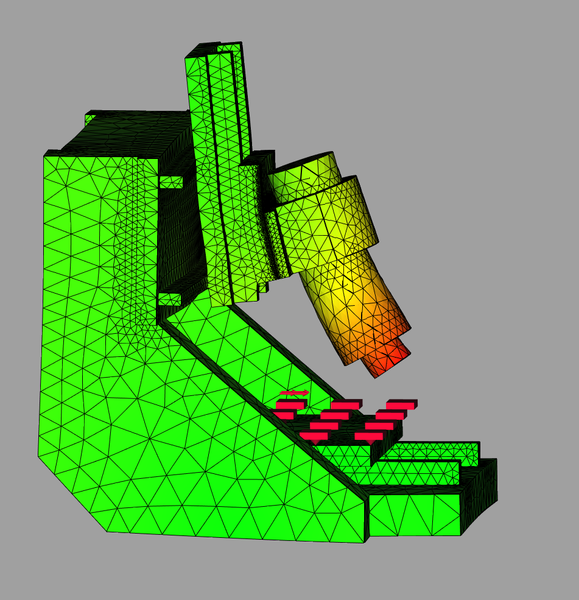
Now I know the spindle motor in real life is much stiffer than this one. But still, maybe I should be clamping the spindle motor much further down? I think I was trying to maintain 150mm Z clearance of everything except the spindle, but maybe that is unrealistic.
The 6040 achieves this by having the spindle clamp offset from the Z linear bearings:
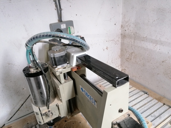
But it looks like the Z plate would be a source of flex there. I think I would actually rather have the spindle clamp higher up, because the spindle motor is stiffer than the Z plate.
And to be fair, with only 200mm of Y travel, and the way I have it set up now, only the rear 44mm of the table can ever hit the gantry anyway! So maybe I can drop the gantry quite significantly without really affecting usability. Leave the spindle motor where it is, but drop the gantry so that it is clamped near the bottom. I just need to make sure I will still have clearance for machining on the 4th axis. I can extend the Z axis upwards if necessary. If the Z axis gets taller I don't think that really affects rigidity in the common case, it just gives me more options.
And dropping the gantry means the uprights (of which there are 4!) use less material, which may be helpful because it gives me more spare material for adding stiffness.
I've dropped the gantry by 50mm.
Now we have:
So that is a big improvement in X and Y and a minor drawback in Z. Why is it worse in Z? Is it because the torque on the gantry is now at a more advantageous angle to twist it? I don't really care about making Z slightly worse because Z was already a lot better than the others. This is overall an obvious improvement.
Good progress. I'd still like to get below 0.10mm in every axis though. And obviously re-check that I can actually fit all the parts in the material I have. I'm not so sure about the 40mm extension to the uprights.
< 2024-02-21 2024-02-23 >