Last modified: 2024-02-19 23:32:43
< 2024-02-18 2024-02-20 >The plan is to grind a HSS lathe tool and try again to make a shaft for the escape wheel.
Also, paying particular attention to the most important dimensions, and less attention to the less important ones.
The length between the shoulders needs to be very accurate, the rest of it I can work around.
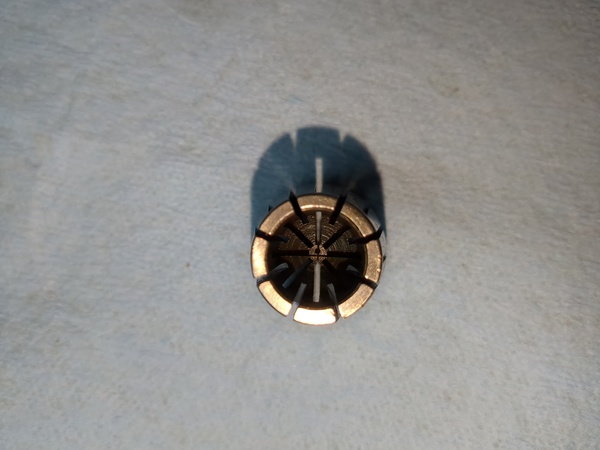
Great, I just opened up the 1mm collet and it is not good:
Well my new lathe tool seems to work well, but I still couldn't make this shaft:
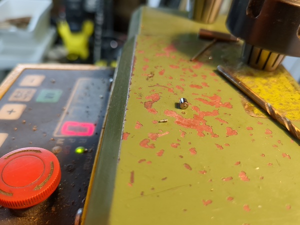
Snapped off during the 2nd operation again. It felt like the steel on the second side was a lot harder than on the first side. I'm going to try again but this time with an unhardened shaft. Also maybe I should purchase some 3mm blued pivot steel, because I'm obviously not capable of making it myself.
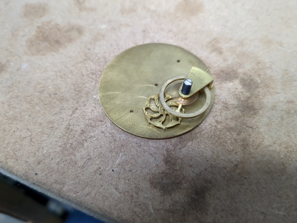
Finally!
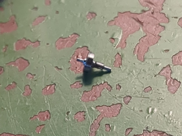
This is silver steel in the soft state, but it is my first "success".
The length of the 1mm diameter section is about 2.9mm, it should be 2.15mm according to the drawing.
I can see visually that the pivots are not concentric, due presumably to the bad collet.
And the section that the escape wheel has to seat on has been crushed by the collet because the steel is too soft.
But let's see if we can work with this for now.
Firstly the balance wheel has to come off and I need to open up the pivot hole in the mainplate to accept the pivot on the shaft.
Then I need to bore out the escape wheel to fit the shaft, and fit it to the shaft, and then see if the escape wheel fits underneath the balance wheel, and then see if it engages with the rollers.
Then if all looks good, give it some finger pressure and see if it works? May need to drill a new hairspring hole a bit lower down, to stop it rubbing. May need the bridge before I can tell whether it works.
Great, snapped the tip off the drill bit instantly.
OK, I managed to get the pivot in the hole, and got the escape wheel fitted to the shaft:
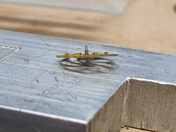
And got it installed in the plate:
Observations are:
The pallet got bent upwards when I tapped the balance wheel onto the shaft.
I have now tried to bend the pallet back down, but broke it off.
So let's work out why the locking teeth do not engage. Possible theories include:
It looks like the holes are 8.30mm apart, the balance shaft diameter is 1.25mm, and the tips of the escape wheel teeth are at 7.80mm radius.
But that doesn't add up because 7.80 + 1.25/2 = 8.425, which means they should intersect.
It is hard for me to measure this stuff accurately. I'll try again.
Well then it should still intersect! I'm going to reassemble it and see if I can see what is wrong.
OK! I've learnt something. The balance shaft is not concentric with its pivots. If I rotate it one way then it engages with the locking teeth, and if I then rotate it the other way to let the tooth through the cut-out, the next tooth doesn't engage on the other side. So potentially if I just re-make the balance shaft and try to make it concentric, it will work??
Looking in 2024-01-07, when I first made the balance shaft, I had the expectation of scrapping it anyway, although I don't appear to have been aware of the concentricity issue.
I definitely need to scrap it now because it no longer has the impulse pallet. I'm going to pull the hairspring and balance wheel off it and have a closer look.
Yes, I can easily see the concentricity problem with the loupe. I'm curious about how this happened. Did I make this surface on the router instead of the lathe? I would have thought I only made the cut-out on the router but made the actual diameter on the lathe?
It looks like it was made with the router to be honest, because it has that tell-tale vertical line where the tool plunges into the work. So I can do the same part again, but next time in the CAD model that I use to make the rollers, I need to make sure it clears the locking diameter.
So that's the next step: re-make the balance shaft, make sure the locking diameter is formed on the lathe and not on the router.
I did wonder if machining aluminium with the CNC router would go any better if I used the same feeds/speeds that I would have used on the milling machine, i.e. 2100 rpm, and whatever feed rate the calculator suggests. So I'll give that a go.
It's possible that it won't work very well, for example if high spindle speed is a substitute for rigidity.
2100 rpm, 220 mm/min, 4mm 4-flute tool, full slotting, calculator suggests 1mm depth-of-cut, but I'll start with less.
Yes, very grumbly. Let's try 4200 rpm, 440 mm/min. Still grumbly. I found that about 10000 rpm and 440 mm/min worked better. So yeah, on the router, you want to have much less chipload than on the milling machine, because it doesn't have enough rigidity. Makes sense.
I've done some approximate CAD of the laundry basket, because I think I might want to put the new machine in the same enclosure:
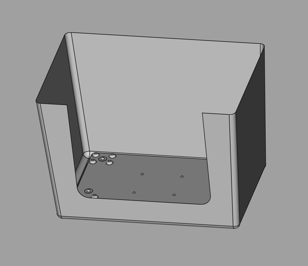
In ~/cad/micro-milling-machine/laundry-basket.FCStd.
One reason to not want to use the existing enclosure is that a gantry machine generally wants the gantry to be as short as possible, so you'd want the Y axis to be your long axis and the X axis to be shorter, but the laundry basket is laid out for the opposite. If I put the gantry the other way round then it would interfere with axis to the table, sounds very annoying.
Reasons to want to keep the laundry basket enclosure are that I could keep the existing flood coolant without making any changes, and it already has a very sturdy steel stand.
Here's a start:
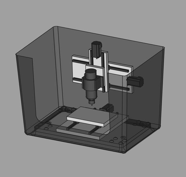
I have separated the moving parts (e.g. the table against the base plate) by the thickness of the rail plus carriage, but the ballscrew with its bearings and ballnut holder is actually much taller, so as I've designed it here both the BF12/BK12 bearings and the ballnut holder would need to sink into the parts they are mounted to. Not obvious what is best. Need to be wary of reducing thread engagement when I sink things in.
This has 300mm X travel, 200mm Y travel, and 150mm Z travel. The table is 300mm * 200mm.
I still need to add: