
Finite Element Analysis is a way to calculate the stresses and strains on an object in various load conditions. The object is modelled as a series of "finite elements" (in our case triangles), and then we specify the locations of points that can't move (fixed points), and the locations, magnitudes, and directions of forces that are present.
I've recently been doing a Coursera course on engineering: Machine Design Part 1 (although it is mostly above my head currently; I think I have missed one or two of the prerequisites), and it has inspired me to try to do some actual analysis of the racing lawnmower chassis, to inform the design of some improvements.
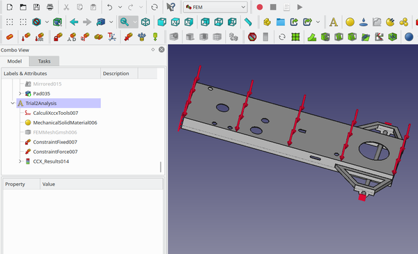
FEA in FreeCAD
FreeCAD has support for FEA in the FEM ("Finite Element Method") workbench. It isn't exactly hard to use, although I found the interface was not very discoverable, and I had to learn how to use it by watching YouTube tutorials. Before starting you need to make sure that you have CalculiX and Gmsh installed.
I have found that CalculiX sometimes complains about "non-positive jacobian determinants" in the analysis. I'm not entirely sure what this means, but it seems fine to ignore the warning. In previous FreeCAD versions this was fatal and would cause FreeCAD to fail to show the results, but in the latest version it seems not to matter. I don't know.
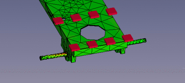
I have also found that Gmsh is sometimes unable to produce a mesh. You'll know this has happened if, after trying to create the mesh and being told that it was created successfully, you are not presented with a visible mesh. You can also check this by looking at the data display for the generated mesh and observing that it has 0 edges, 0 faces, and 0 vertices. If this happens I have found that putting a cap on the maximum element size tends to help Gmsh along (I start high and keep reducing the cap until it works - using smaller elements takes longer to mesh and longer to analyse). You may notice that some of the pictures in this post have much denser triangle meshes than others; this is why. I don't think mesh density would significantly affect the results, other than that a denser mesh will be slightly more accurate.
A limitation of the FreeCAD interface is that you can't apply a force to a small area of a large face. If you want to add a 4,000 Newton load to the top of a flat plane on your chassis, FreeCAD is going to distribute it over the entire area and provides no way for you to localise the force to a smaller area. If you really need this, a workaround is to extrude a very short pad (say, 0.01mm tall) in the area you want to apply the force so that you get to define the shape and size of the force area without significantly affecting the mesh of the part. I didn't bother with this.
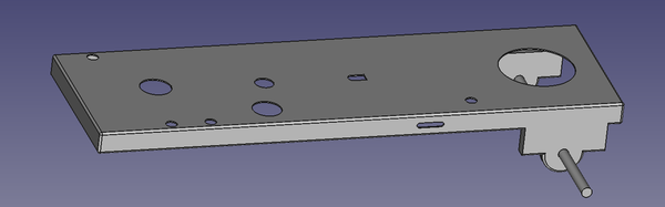
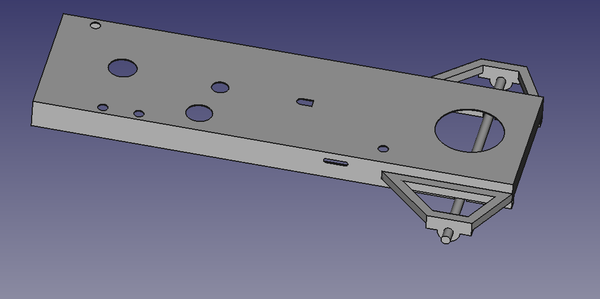
Lawnmower Chassis
I started by measuring the key parts of the existing chassis and modelling it in FreeCAD. Most of the chassis is made of 3mm steel sheet, and the rear axle is 25mm steel round bar.
I left off the front axle because I'm confident it's completely overbuilt, and I left off everything above the main plane of the chassis because it isn't interesting and doesn't really contribute to the strength.
Now comes the hard part: we need to define which faces we want to say are "fixed", and which forces we want to apply, to find out how the chassis will be stressed. It is easy to create completely unrealistic load scenarios so this really takes some thinking about. For example, initially I thought a good way to model stress in the rear axle would be to fix one end of it and apply an upward force at the other end, but this is actually not realistic at all because if sufficient force is applied to one end of the axle, it will result in movement at the other end. I've found it helpful to imagine the "fixed" face being firmly attached to a wall or ceiling (upside down if appropriate), and then a weight being hung off the force area. If that's not an accurate way to model how the chassis will be loaded in use, then it's not an accurate way to model it in FEA either.
Initial tests
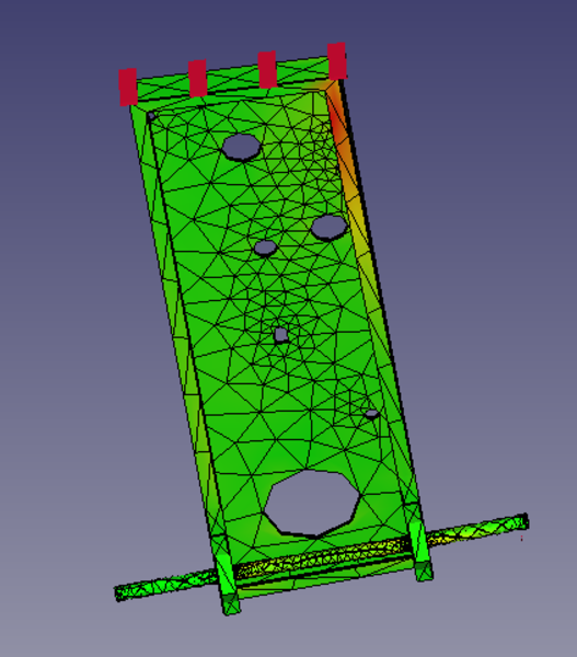
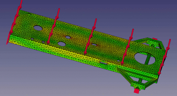
The highest stress observed across the 3 test cases was with the top of the chassis fixed in place and an upwards force on one end of the rear axle. FreeCAD has an option to exaggerate the displacement caused by the applied force to make it easier to see what is happening. Here I have animated together the displacements from 0x to 10x what was observed from a 4000N load.
The colouring goes from green where there is no stress to red where there is maximum stress. In this test the greatest stress observed was 485 MPa, and it was at the top and bottom of the rear axle. 485 MPa exceeds the typical yield strength of steel, so in the case where the mower chassis is attached to the ceiling upside down, and the entire weight of the mower and driver is hung off a single rear wheel, we can expect the rear axle to bend. Not good.
In practice I don't think it will be this bad because we never have a force against a wheel while the rest of the chassis is held fixed. In reality the axle is able to push the rest of the chassis out of the way, so I think the actual stress in the axle would be less. Which is why it hasn't bent yet. Nonetheless, it would be good to move the bearings outwards so that the axle is better supported and can transfer load into the chassis instead of bending.
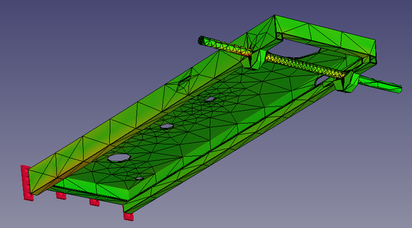
Another test (although not one I'm particularly convinced by), revealed that the lip along the bottom of the chassis can be heavily-stressed in certain conditions:
This test has the front edge of the chassis fixed in place, and a 4000N force upwards on the left edge of the rear axle (right in pic). It's an unrealistic model because a 4000N force on the rear axle would be enough to pick up the rear end, rotating the entire mower around the front axle. The front end wouldn't remain fixed in place. But the test still highlights a potential weak point.
Also note that this picture has had the rear axle raised up towards the chassis to reduce ride height. This is a change we definitely want to make, so all of the rest of the analyses have the axle in this new location.
Strengthening the sides
An easy way to strengthen the sides of the chassis is to weld some box section to the bottom of them. Here I've added lengths of box section 25mm across with 2mm wall thickness:
The maximum stress (in the admittedly-dubious test) is reduced from 813 MPa to 510 MPa (-38%), and the area of max. stress is no longer on the lip underneath, it's now the axle, so the stress on the lip underneath the chassis is reduced by even more than 38%.
Moving the axle mounts out
To move the axle mounts out I modelled a small frame on each side made of 25mm box section with 2mm walls. The bearing block is then attached to the end (in real life this would be bolted on, but in the model it's all just a solid piece of steel), and the axle goes through the bearing block.
With the top plane of the chassis fixed and a 4000N load applied to one end of the axle (the highest-stress load condition), we get this (displacement exaggerated 20x):
The maximum stress is 424 MPa, at the corner of the frame, where it attaches to the chassis. In the same test on the original chassis model but with the ride height lowered, the max. stress was 496 MPa (in the axle), so adding this frame only reduced the stress by 15%, although it did move it out of the axle. I expected a better reduction though.
I thought part of the problem here might be that the little frame is only attached to sheet metal, which means there's a relatively low joint area between the frame and the chassis, so I tried adding an extra piece of box section to the frame:
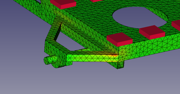
Now in the same test, the maximum stress is 328 MPa, which is now 44% lower than before. Much better. The stress is still concentrated in a small area at the edge of the frame, though, so probably more support here would help even more. When I actually build this, I plan to start with what is modelled here and then overbuild it based on whatever seems reasonable to me at the time. Triangulating the support by adding a tube from the end of the frame to the top face of the chassis wouldn't hurt.
Engine mounts
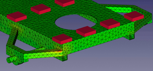
The test with the axles fixed and a downwards force on the top plane of the chassis was quite surprising. In this test the maximum stress generated is quite small (about 80 MPa), but the displacement of the chassis is quite large, because most of the stress is taken up in a large thin piece of sheet metal. Exaggerated 20x we get:
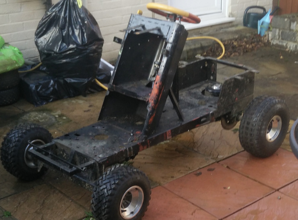
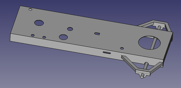
You can see that the sheet metal just flexes with the force applied. The major forces acting in this way are the weight of the driver and the weight of the engine. The driver's weight is distributed to the very edges of the rear of the chassis by the box that the seat sits on, which you can see in this photograph:
So the driver's weight isn't trying to flex the sheet metal. But the engine is bolted to the middle. I think it would be worth adding some reinforcement around the holes that the engine is bolted to, to reduce this flex.
You can also see that the stress is concentrated around the holes in the chassis (the orange/red areas). I don't think this is a problem, because the magnitude of the stress is relatively small, but if I can be bothered I might weld some steel plates over some of the holes just to close them up.