Last modified: 2023-12-17 08:16:34
< 2023-12-12 2023-12-16 >I was wondering if I want to make the teeth inside the inner barrel with an end mill, what module would I get? And if the rest of the train is module 0.2, can I get away without adding any extra gears?
On 2023-10-08 I reckoned that watch-mod02-4.FCStd was the one to go with, so let's start there.
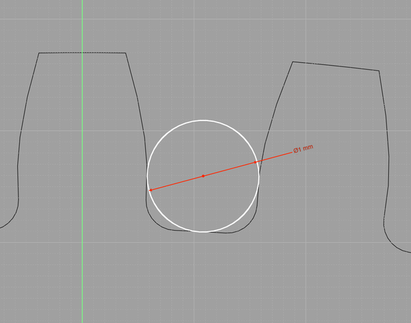
The smallest gear teeth you can make with a 1mm end mill is about module 0.7.
So if I copy watch-mod02-4 to watch-mod02-5, and make the inner barrel gear module 0.7, where do we end up?
The inner barrel gear reduces from 172 to 47 teeth, a factor of 3.65. So we'd need to gain a comparable factor elsewhere.
First wheel changes from 66/8 teeth to 92/6 teeth, gaining us a factor of 1.86, leaving 1.96 to go.
Second wheel changes from 66/8 to 92/8, gaining us 1.39, leaving 1.41 to go.
Third wheel changes from 60/8 to 85/8, which is all we needed.
Here's that, and with the latest escapement:
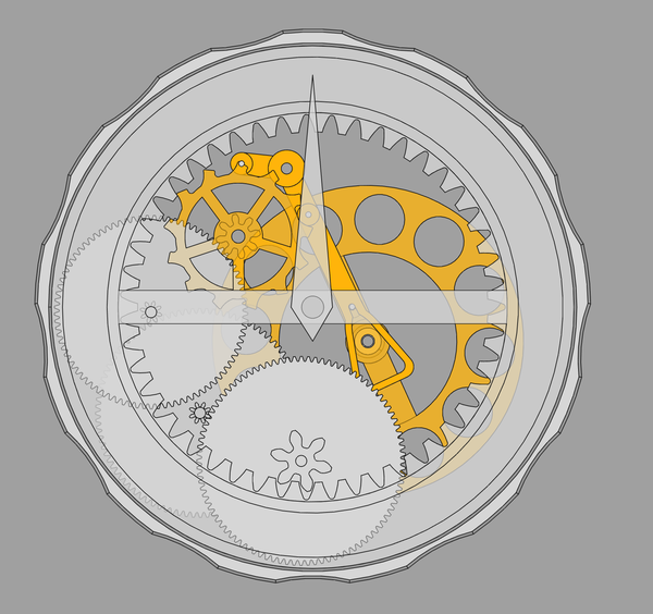
Which... I guess technically fits within the outline, but the balance wheel is obviously too big, and there is only room for one pillar to hold the plates together.
How fast would this have to beat? The barrel turns once in 12 hours, and during that time the escape
wheel passes (47*92*92*85*13) / (6*8*8*8) teeth = 143091 times, = 11924 teeth per hour, and the
balance wheel does 2 beats per tooth, so this is almost 24000 bph, which is a lot more than I think I need.
Did I miscalculate this last time I looked at it?
I could have stopped at changing the first wheel from 66/8 to 92/6, which would leave it at about 12000 bph.
That makes a bit more room, but the escapement is so big that it doesn't make a lot of difference.
In addition to being easier to make, switching to the module 0.7 barrel inner also places the first wheel's pivot further away from the barrel, which is good.
With the second and third wheel reverted to previous tooth counts (giving about 12000 bph), and the balance wheel reduced from 28mm to 19mm, we have:
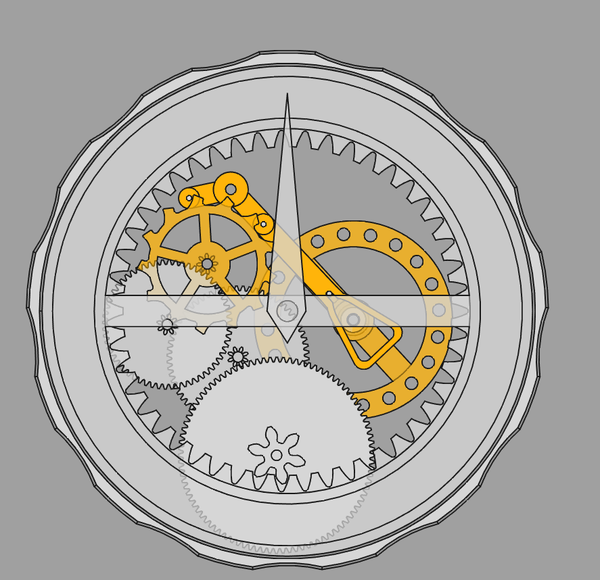
Which now has potential for 3 pillars to support the plates, but probably not enough space spare to put roller pivots for the inner barrel.
And the balance wheel could get a lot closer to the escape wheel now that it's smaller. (Or, it could get slightly closer, and slightly less small).
It occurred to me that we could have this pallet fork even if the balance wheel is pivoted into the same plates as everything else, as long as the motion of the pallet fork keeps the balance wheel shaft inside its slot! It's shaft-passing-adjacent again. Sadly the current design completely passes to the other side of the balance wheel shaft, however most of that space is just clearance, to avoid the banking issue, so we could potentially give it even more clearance? Lol.
We do have a problem with the escape wheel interfering with the third wheel shaft. But only slightly, maybe just swap the second and third wheels?
What is the benefit of the balance wheel being hollow? Would a solid disc work better, on the grounds that it has a higher moment of inertia? Is the issue just that a solid disc is needlessly heavy? I don't think I care about that. If it gets me a higher moment of inertia with a smaller diameter I'll take it.
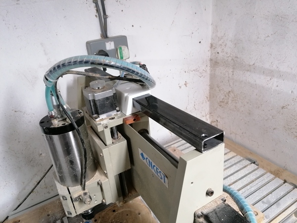
I'll need to get some sort of linear rail maybe 520mm long. I have some box section 40mm by 20mm to attach it to.

I propose cutting the sheet metal so it only covers the back and not the top, then bolt the steel box section to the top of the gantry, and fit the linear rail to it.
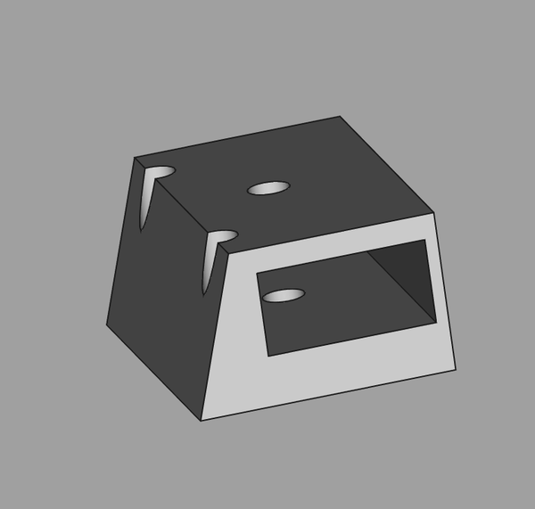
And then I'll need to make a bracket to attach the linear bearing to the carriage.
The X axis travel is about 400mm, so a linear rail that can accommodate 400mm of travel would be sufficient.
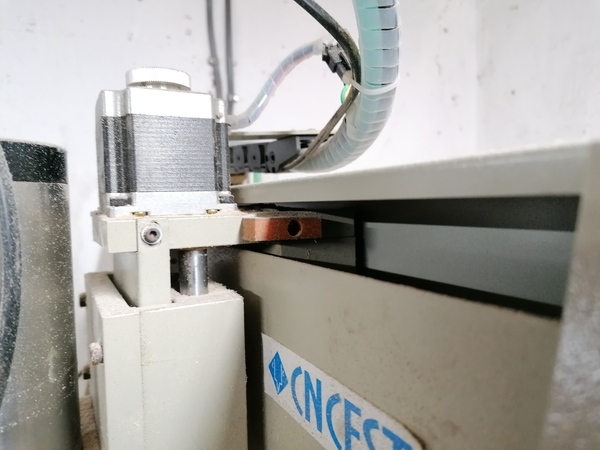
I could make a start by simply fitting the steel rod and 3d-printing a "bearing" for it, and see if that reduces the flex at all.
With this setup:
And pulling the collet nut back and forth by hand, I can easily get a total range of 0.5mm at the dial indicator. The steel isn't even bolted down yet.
I'll cut it to length, bolt it down, and 3d print a bearing to fit to the carriage, and measure it again.
Not very fancy, but it's not permanent anyway. Unless I identify an obvious problem, I'll probably replace with some sort of "proper" linear rail.
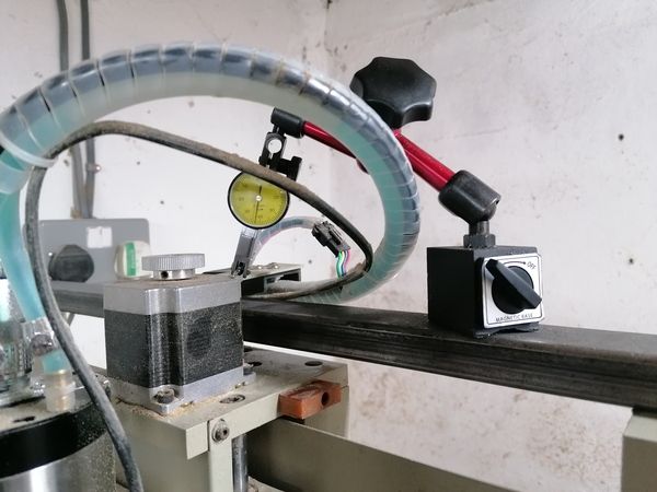
This actually works pretty well:
With the same dial indicator setup as before, I get a bit under 0.1mm total range on the dial indicator. It is now obvious that the Z axis is the most flexible bit rather than the X axis.
Actually the Y axis is quite flexible too. I think because there is only one ballscrew, in the centre, so the sides can move. If I put the dial indicator on the tool and pull back and forth on the collet nut I get over 1mm of total movement.
Since the X axis is no longer the weak point of the machine, I'm not going to bother buying a proper linear rail, this is more than adequate.
I looked in the box of watch parts and took out a big-ish gear. It is a lot smaller than my module 0.2 gears!
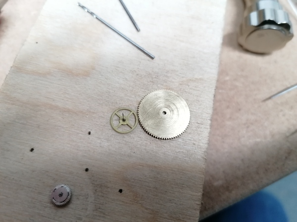
Looks like the teeth are 2 to 3 times smaller.
The gear is about 0.16mm thick, the shaft is 0.33mm diameter, and the pivots are 0.23mm and 0.12mm diameter (different at different ends).
I'm going to try cutting some new 77-tooth module 0.2 gears, but using the cutter made on the router. Hopefully should get a more convincing tooth profile.
Then I want to make a smaller fly-cutter holder and make a cutter for matching pinions.
I've hardened the new end of the cutter, this time using a ceramic pot instead of a plastic one. The end still looks nice and well-defined.
Damn, the angle-grinder relief on the new cutter is not enough! It is cutting the tips off the gears. I'm going to try and rectify it, but it may scrap the teeth I've started cutting. All the more reason to make the new holder.
It looks like it is quite badly off the centre line, so all the teeth are angled. Bad.
I dropped the cutter taking it out of the spindle and I'm pretty sure I chipped the end.
I think I have got the shape of this cutter wrong, the dedendum gap is much narrower than the tooth. There is no chance of a tooth fitting in the gap.
It's just a 12mm EN1A rod, with a M4 thread up the end and cross-drilled to hold a 3mm cutter.
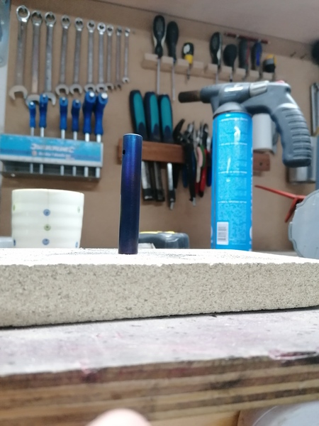
I blued it, for the practice: