Last modified: 2023-10-13 15:14:30
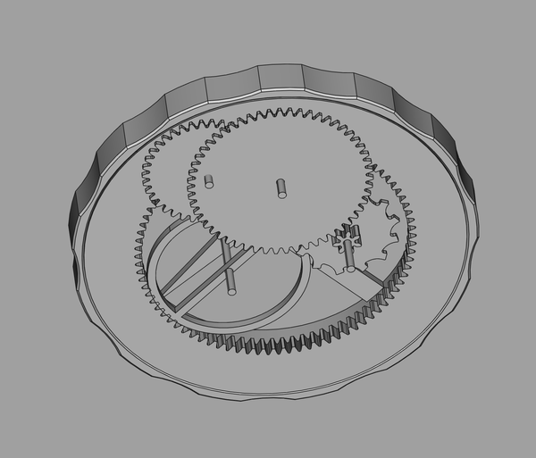
< 2023-10-07 2023-10-11 >I was experimenting with laying out a movement for about 8000-10000 bph using module 0.4 gears.
One problem I keep running into is that if a gear later in the train is larger than an earlier one, then they interfere:
The shaft for the smaller gears passes through the same space as the larger gear.
The obvious solutions are:
Making the gears always decrease in size is not good for this layout because the first gear's size is limited by the thickness of the barrel. We want to make the barrel thin, so that there is more space inside, but we want the first gear to be big, so that we don't need so many.
Using separate bridges is a lot of effort and will add thickness, so I also want to avoid that.
So... what do? Is there a third solution? What if there is an idler in contact with the barrel, and the idler turns on a screw instead of an ordinary pivot? It is screwed into (a standoff on?) the top plate, and the "real" first gear of the train can pass over (under...) the head of the screw? And then the first gear gets to cover the thickness of the barrel plus the diameter of the idler.
I think it is OK for the idler to run on a screw instead of an ordinary pivot because it is at the start of the train where there is the most torque available.
The configuration above (with interfering gears) would need 1100 bph, so I need a factor of 8 on that.
Let's have a look at adding an idler that runs on a screw...
(watch-mod04-2.FCStd)
Well it certainly helps with geartrain layout.
But I'm not sure there's going to be enough room for the escapement:
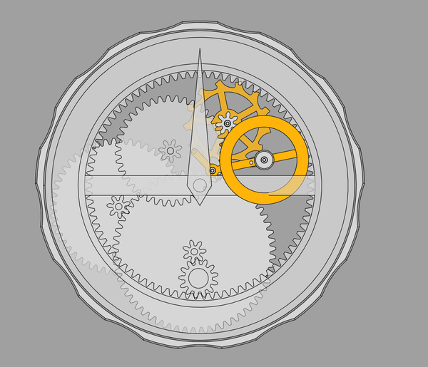
Even with the tiny balance wheel from the metal escapement model, it looks like it wouldn't really fit. Even if you make it fit, there's barely any room left to connect the upper and lower frame plates.
So what if we try the same kind of idea with the idler, but module 0.2?
(watch-mod02-3.FCStd)
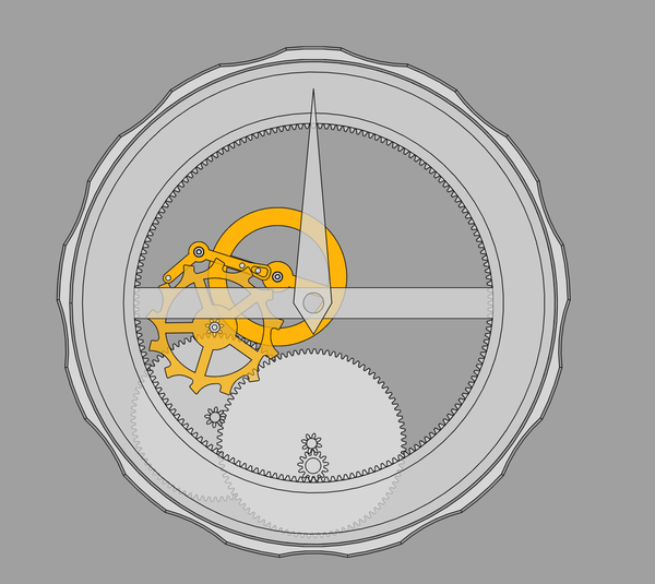
Loads of room, even for a much larger balance wheel, and no interfering shafts.
This would be 5240 bph with 8-tooth pinions or 7820 bph with 7-tooth.
We can't lose one more gear, because then the remaining one would need 900 teeth.
And finally, how does it look if we lose the idler and add one gear? Arguably that would be an improvement from a friction standpoint as the extra gear would have a better pivot than the idler.
(watch-mod02-4.FCStd)
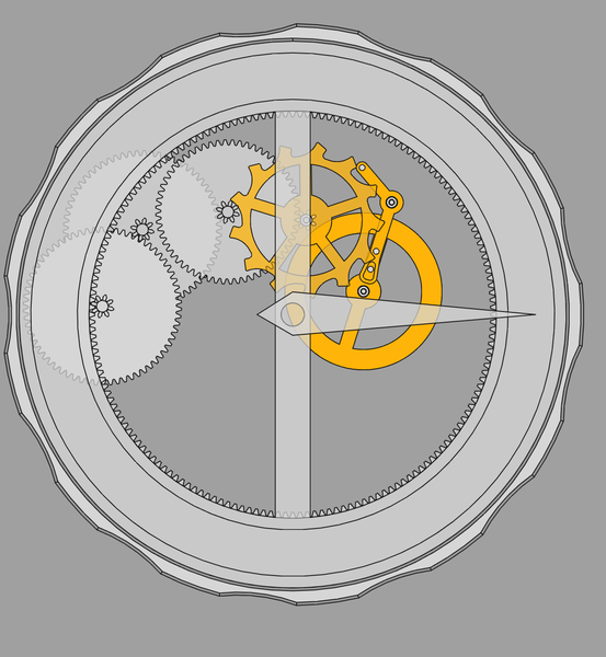
This is about 22000 bph, which is way more than necessary, even with 8-tooth pinions.
So I think this is the layout to go with. If module 0.2 is too much trouble, we can go to module 0.3, and 7-tooth pinions if necessary.
Remaining problems:
I had another go at making the escape wheel shaft.
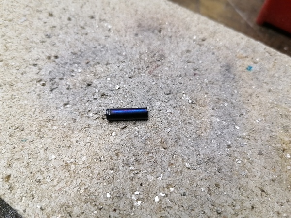
Bluing the bit of 4mm rod went well again, this bluing is way easier than I thought:
I also tried it out on a much larger part, using the big blowtorch, just to see if it would work:
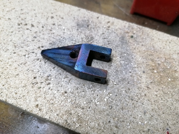
Great success! I should start bluing all of my steel parts.
I broke the shaft again while trying to make it though. I broke it while turning the 0.5mm pivot after having already turned most of the shaft down to 1mm. It occurred to me that I should turn the pivot on the end before turning the rest of it down, that way I can keep the strength for longer.
Rather than go to all the trouble of turning the 4mm rod down again, I decided to try again using 1mm blued pivot steel. Obviously it won't have a blank for the pinion, but I should at least be able to see the escape wheel run in its pivots.
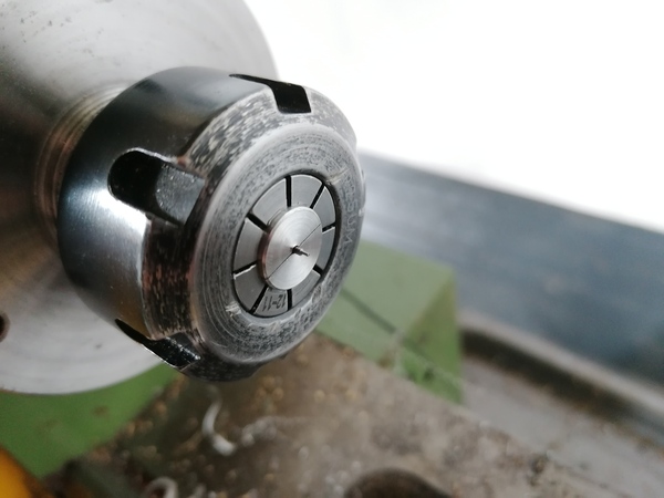
I necked down the 1mm collet, and extended the cut (although not very straight):
The idea being that it can "bend" at the junction between the narrow bit and the wide bit, and might seat better against the 1mm rod. Maybe.
Also I re-ground the parting blade to try to make it turn square shoulders, but was not wholly successful.
This time I really choked up on the shaft, and it went much better:
One shaft ready to be fitted to one escape wheel!
I held the shaft in the pin vice and sanded off the bluing:
I had to drill the hole in the gear out to 1mm, but obviously overdid it. I need to make a slightly-undersized 1mm reamer so that I can create these 1mm press-fits.
I positioned the gear over the 2mm hole in the block, and pushed in the shaft by hand with the pin vice. It was initially tight (a burr on the shaft? must remember to get rid of this), but then became too loose, so I had to glue it in place with Loctite 603. I must get better at making the press-fits.
Next step, try to put it in the frame and see if it will spin nicely in its holes.
Looks pretty good. Spins quite well too, although sometimes binds up, probably because the pivots have a radius at the connection to the main shaft, which can bind up in the hole. Also it's slightly out-of-concentric, which we already knew.
https://www.youtube.com/watch?v=Y_LXHe8_6tY
So improvements required are:
Next up is probably to try and make the pallet fork so that I can manually work the two parts and see them interacting.
I rubbed a piece of 1mm blue pivot steel against the oilstone with a slight taper to make 6 flat surfaces:
It has some tape on it so it doesn't get lost amongst the other piece of 1mm blue pivot steel.
And then I tested it by drilling a 0.9mm hole in some 1mm aluminium sheet, reaming it a bit with the reamer, and then tapping in some 1mm blue pivot steel with the little hammer. It works pretty well and seems like it would give an acceptable fit. Just need to be very careful not to ream the hole over-size. Also it's hard to tell whether the hole is reamed to the correct size without trying to hammer a shaft through it, which could result in getting the shaft stuck in a hole that is too small. Also not sure it's acceptable to hammer on a 0.5mm pivot, so maybe need to make a little punch with a 0.6mm hole in the middle that I can tap it in with.
Ideally it would have an even shallower taper, but it is pretty hard to get a consistent angle by hand against the oilstone. Maybe I should put a little Dremel grinding wheel in the router, and use the rotary axis to grind some flat surfaces at a slight angle? This will do for now though.
Let's try and make the pallet fork next.
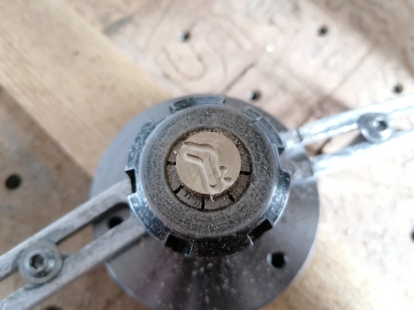
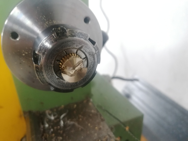
I'm going to use the same technique as the balance wheel, of machining it on the end of a bar held in the collet, and then parting it off on the lathe.
This time I'm going to deliberately machine it deeper than required, so I don't feel under so much pressure when facing it to length.
I really like this technique, because it means the part is rigidly held the entire time, no matter how thin it gets, and no matter what order you do the operations in (i.e. it remains attached firmly even if you do the outer profile first).
Machined the profile with the 2mm 1-flute tool, 150 mm/min, 14000 rpm, 0.25mm step down:
Drilling holes went without drama, I used the PCB drills obviously, running at 2000 rpm for the ~1mm ones and 3000 rpm for the ~0.5mm ones. Feed rate set to 10 mm/min, and clicking the Z feed in 0.1mm increments.
I drilled holes to start the slot off to reduce the load on the 0.6mm fibreglass-cutting tool.
Holes drilled were:
X0 Y0 (pivot hole)X-3.44 Y-1.88 and X3.85 Y-2.16 (pallet pin holes)X4.945 Y-2.774 (small end of slot)X5.73 Y-3.215 (big end of slot - but check this one, not sure)I finished the slot with the 0.6mm tool, with 0.1mm depth of cut, and some full slotting, at 24000 rpm and 16 mm/min feed rate. I went very slow on the feed because I was worried about breaking it when it has to do the tiny amount of full slotting in between the drilled holes, but it didn't show any signs of trouble and didn't break.
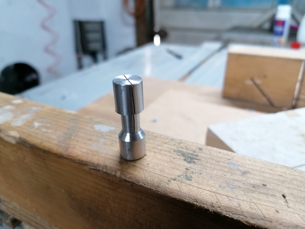
Taken to the lathe, faced, parted, glued, and faced:
Sanded and polished and cleaned:
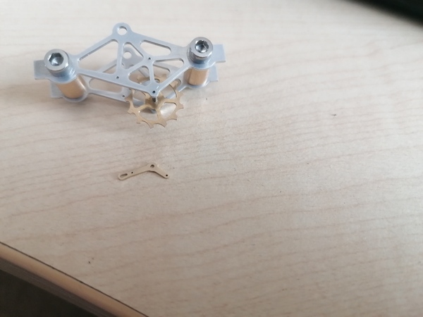
Great success. This workflow is quick, easy, and reliable. Where possible I should favour making flat parts instead of shafts.
I'm pleased that this part is made, because so far it is the smallest part that the watch will need. (Although there may end up being smaller ones for the ratchets).
mk-gear for concentricity)