Last modified: 2023-12-13 09:21:28
< 2023-12-10 2023-12-13 >I think today's plan is to make cutters for cycloidal-ish wheels and pinions at module 0.2, and then try to make some gears, and make a frame to let them mesh together. I should make the frame oversized so that I can add provision for a mainspring and escapement at a later date.
So what geometry do I need for a cutter for module 0.2 gears?
Stan Bray's "Making Clocks" says that for modules "0.45 to 1.1 to 1.5" the addendum radius should be 1.93 times the module. He doesn't say how it varies outside this range.
But if that were true, the radius would be 1.93 * 0.2 = 0.386. Which would need a cutter small than 0.8mm to make.
But I don't trust his numbers at all, because for example he says "full tooth depth" is 2.95 times module for modules 0.45, and 1.1 to 1.5, but is 3.38 times module for modules 0.5 to 1.0. Why the discontinuity? I think he has badly misunderstood something.
I'll read this Designing Cycloidal Gears page.
Oh, skip reading that, he has a Cycloidal Gear Calculator
Sadly this says the addendum radius is 0.44mm, I certainly don't think I have a 0.8mm cutter that I can cut steel with. Let's just try and work something out.
Well I tried to use the 0.8mm fibreglass cutting tool and it broke :(. I was trying to use 10mm/min and 0.1mm depth-of-cut.
However it might have made a workable cutter before it broke! Let's just try and make a gear and see what happens.
I have realised that my "small" fly cutter holder is way too big for watch stuff. It takes 6mm square blanks, on which I am making cutting tools less than 1mm square. I should make the micro-milling machine.
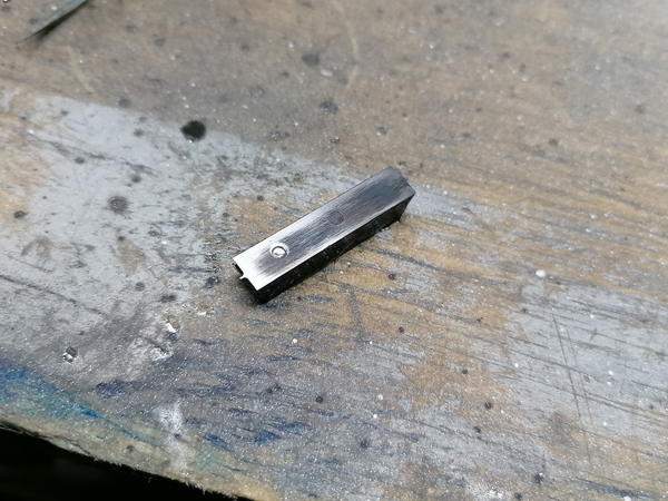
Before making a gear I should try to harden this cutter. It is O1 tool steel apparently. I think just get it glowing red and then dunk it in oil. I used the 80W-90 gearbox oil, for no particular reason. I used a plastic container which was a bad idea as it melted a hole in the bottom, but thankfully the oil didn't escape too fast.
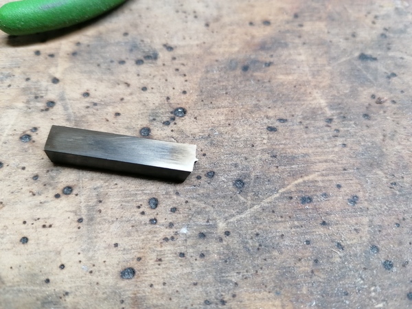
Well here is my cutter:
For 80 teeth at module 0.2 the addendum is about 0.3mm and the pitch circle is 16mm (according to the csparks calculator). I have some convenient 16mm stock, so I'll do 77 teeth, which gives a 15.4mm pitch circle, such that the overall outer diameter is 16mm.
And I'll try to setup the 4th axis concentric. I bumped it around with the drift and it seems within 0.05mm TIR.
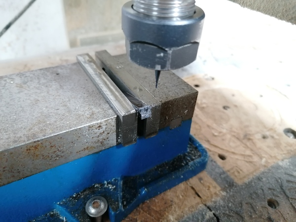
I need a better procedure for centering the gear cutter in the Z axis.
Great success, one 77-tooth module 0.2 gear blank:
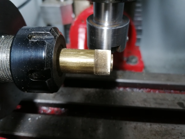
Probably get a few out of that. Now I'll move to the lathe, drill a 1mm bore, and part off discs until I run out of toothed shaft.
3 gears parted off:
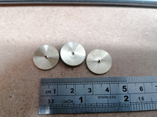
Parting them off went quite fast. It would definitely be advantageous to arrange that all of the gears in the watch have the same module and same number of teeth, to speed this up. Could potentially even cross them all out in one go, though maybe too risky.
I'm going to clean these gears up, then put some drill bit shafts through them into a wooden board or something and see how they mesh. I could do with a depthing tool.
They mesh pretty well:
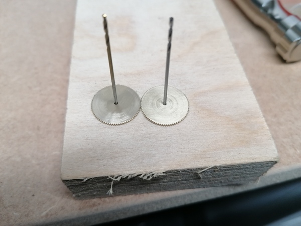
The holes are about 15.7mm apart, which is a bit more than intended (should be 15.4mm as per the pitch circle). But looking through the loupe I can see some burrs on the teeth. How do I clean these off? Even my needle files are too big.
It looks like they don't mesh at 15.4mm centres. The teeth look to be too short and fat. I think the radius on the cutter is too big? There is a brass witness mark on the cutter suggesting that the part with the 2mm radius has been touching the brass. I.e., because the 0.8mm end mill broke before completing the part, some of the cutter has 2mm radius instead of 0.4mm. So probably that is at least part of the problem.
Forcing them to mesh at about 15.4mm and then running them together seems to be the best way to clear out the burr.
According to csparks calculator, for a module 0.2 gear with 77 teeth I need an end mill just under 0.95mm diameter. For 6 teeth I would need 0.66mm diameter. Having tiny end mills like this would be handy for making other parts as well, so maybe I should try to get some, instead of using the fibreglass-cutting tools.
But for now I can try to re-make the existing gear cutter, using a 1mm end mill in the router, just to quickly decide whether the router is stiff enough to cut steel with these tiny tools. First I will try to anneal it by heating way past blue and letting it cool in air, and check that it is soft with a file.
Online it says that annealing steel requires very slow cooling, like several hours, so maybe it would be better to just cut off a fresh piece of steel. I'll let it cool for a few minutes and see how soft it is.
I think the end I hardened properly is still pretty hard, so maybe annealing it hasn't worked. Oh well, the other end is soft enough to file, so I assume it's soft enough to machine.
Great success, it worked really well. I got some chatter while manually jogging to cut the end of the material, but it didn't break the tool. I ran the G-code with 24000 rpm, 100 mm/min, 0.1mm depth-of-cut, and some of it was full slotting.
The 1mm end mill only has 3mm of flutes, so I hacked the bottom off with the grinder.
It is visibly a better shape than the one made on the milling machine. I think the milling machine leadscrews are not precise enough.
Must remember this needs hardening before using!
I've read a bit more of Gould, and come across Berthoud's detent escapement:
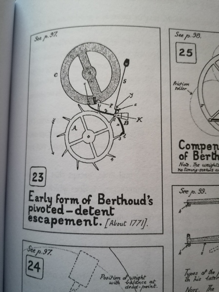
This looks even simpler than Le Roy's! The impulse pin c is beveled on its "back" side
so that on the return swing it lifts the detent arm z away from the balance wheel axially.
So the detent arm is its own spring.
On the forward (clockwise) swing the impulse pin c pushes the detent arm z anti-clockwise, unlocking
tooth 3 from the locking pallet l, and allowing the escape wheel tooth 1 to push the impulse
pallet p.
Once c is clear of the detent arm z, the spring S pushes the detent arm y back against the stop
at s, ready for locking pallet l to catch tooth 4.