Last modified: 2023-12-10 19:59:45
< 2023-12-09 2023-12-12 >I replaced the 12v transformer with a 6.3v one, hopefully it cures the buzzing issue.
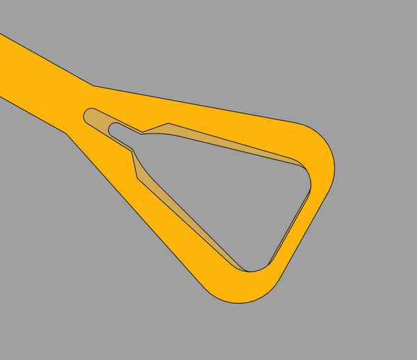
I've made the slot bigger to try and stop it rubbing:
And I'm going to 3d print it. I'm wondering if I should increase the flow rate or something to make the prints with the 0.25mm nozzle a bit stronger.
The larger slot was a small help, but I discovered the real problem: the impulse pin was leaning to one side. I've straightened it up and the balance wheel can now swing back and forth freely, pushing the lever as it crosses the centre point. Great success, does it tick now, or is there more?
Yes, it ticks a bit when powered by hand, but keeps stopping. I'm going to make a little hook on the string and power it with some nuts.
It's very close but not quite working. The interaction of the escape wheel and pallet pins may be not quite right.
In this pic:
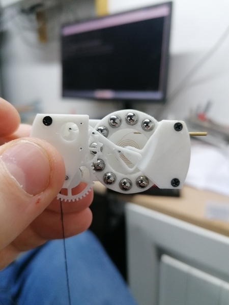
(Both the escape wheel and the balance wheel are trying to move clockwise at this point).
The movement is locked up because the discharging pallet pin has not banked all the way into the root of the tooth, so when the receiving pallet pin tries to move back down it is blocked by a tooth.
The balance wheel is unable to move clockwise, because the impulse pin can't move the lever, because the receiving pallet pin is stuck. But why didn't the escape wheel move round further? "Lack of torque" is one explanation, but here I have an M20 nut on the end of the string, which should be more than adequate.
I think the issue is that both pallet pins are in contact with the escape wheel at the same time. The escape wheel is prevented from moving by the receiving pallet pin, which can't move up because the discharging pallet pin is already banked against the wheel.
But why? I think the pins are not perpendicular enough and the escape wheel is not printed with sufficient quality. Maybe the escape wheel is also not concentric to its shaft.
But we are making progress (slowly). The balance wheel is good now, and the impulse pin can move the it back and forth via the slot. But the impulse pin still rubs on the top of the slot, and the pallets & escape wheel don't work.
That the impulse pin rubs on the slot and the lever doesn't always move far enough to let the escape wheel turn could both be caused by the same issue. Namely the escape wheel is too poor, or is not concentric enough. So maybe I try to take the escape wheel off the metal escapement and fit it in here.
Yep:
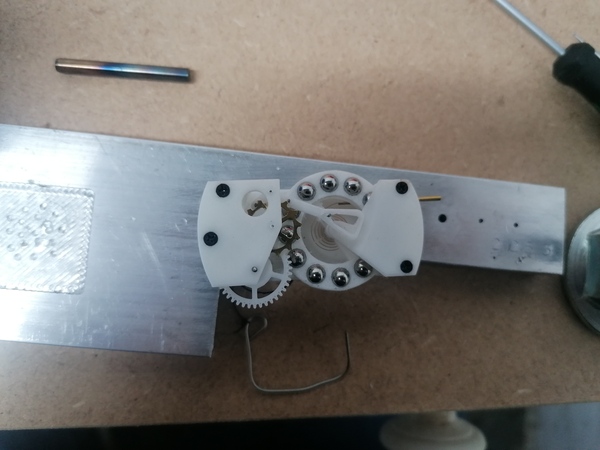
And this is so close to working. With an M20 nut I have observed it tick for nearly 50 consecutive cycles (100 ticks). OK, they weren't particularly convincing ticks, but they were ticks.
I think there is definitely still some concentricity error in the escape wheel because the "impulse pin rubbing in slot" condition occurs intermittently, presumed in sync with the rotation of the escape wheel.
And obviously it needs to run with significantly less weight than the M20 nut, but even this would be a good start.
I tried to record a video and it worked even better than the first time:
https://www.youtube.com/watch?v=xvNODOp6uBc
Gould tells us that the impulse pin should interact with the lever as close to the dead point as possible, as energy lost/gained at the dead point has the least effect on the period of the balance.
To this end, we would actually want to make the lever shorter rather than longer.
For reference this is the current layout:
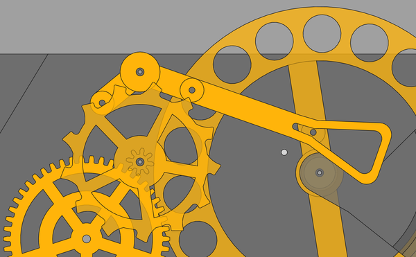
An obvious improvement would be to rotate the pallets around the escape wheel so that the pallet fork shaft is as close as possible to the outside of the balance wheel, such that the lever can be shortened accordingly.
But another improvement would be to have another cock in the plane of the balance cock, with the pallet fork running between this cock and an upper plate, like this:
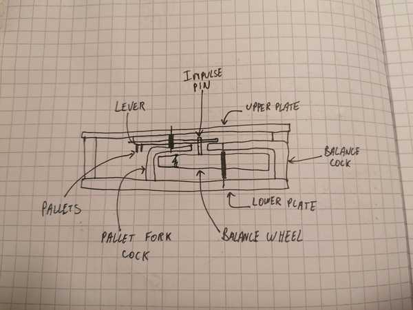
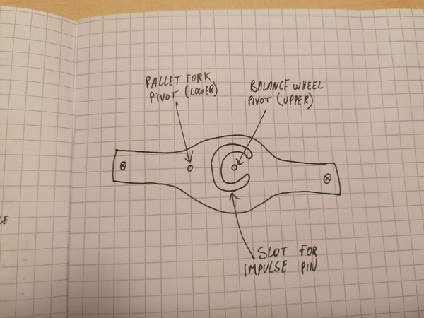
And you could imagine combining the pallet fork cock with the balance cock to make a combined bridge containing the lower pivot of the pallet fork and the upper pivot of the balance wheel. It just needs a slot to allow the impulse pin to pass from the lower side (the balance wheel) to the upper side (the pallet fork).
Gould has this drawing of "Le Roy's detached escapement":
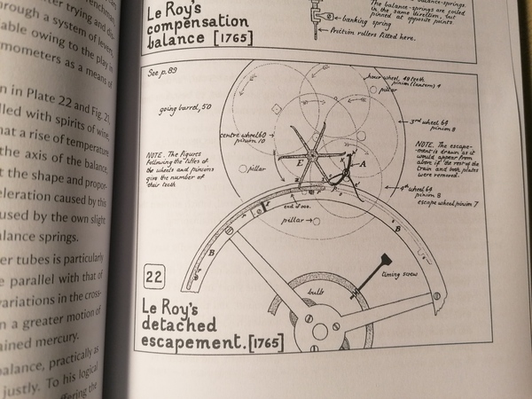
Should I be making something like that? The advantage over my escapement is that it almost completely
eliminates sliding friction against the escape wheel, and it doesn't appear substantially more complicated
to make, possibly easier as there are no pins to try and fit perpendicularly. The only complexity is that
the balance wheel requires machining on both sides (to make the raised arcs marked rrr and ooo, which interact
with the anchor arms c and c'), and the anchor has features at 2 different levels (pallets p, p' and
the arm c' on top, and the arm c underneath). Also that the unlocking of the escapement and the providing
of impulse are quite far separated from each other, which seems potentially difficult to setup?
Wikipedia has this diagram of same:
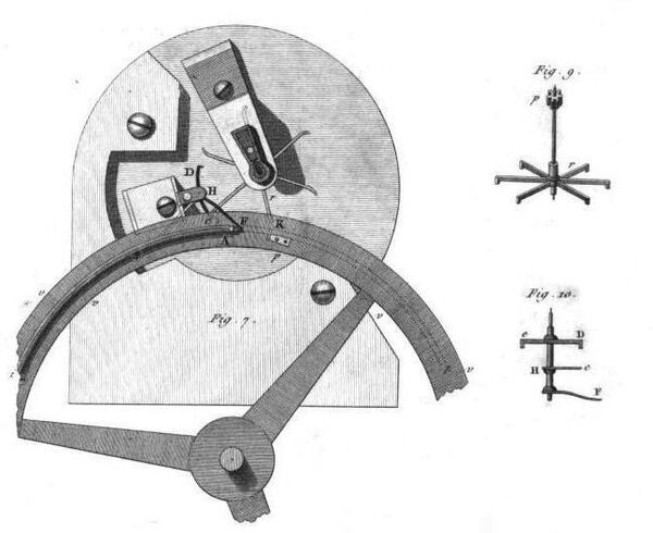
The Wikipedia article says Le Roy's escapement is "theoretically deficient", but does not say why, and the cited sources are all books.
For this matter, maybe an "ordinary" detent escapement is actually not that hard to make?
Jacques Favre has a 3d-printed model: https://www.youtube.com/watch?v=PsLbLa05fKg
This video is a great demonstration of how it works, including a demonstration of the "tripping" phenomenon, which occurs when the amplitude exceeds 360 degrees: https://www.youtube.com/watch?v=JSNDjuKPdng
The escape wheel teeth need to push against the impulse pallet which is on the balance wheel, and against the locking face which is on the detent. The escape wheel also has an unlocking pin of some sort, which pushes the detent spring. In one direction, pushing the detent spring just moves it out of the way and has no effect. In the other direction, pushing the detent spring pushes the detent as well, which unlocks the escape wheel, allowing the escape wheel to start turning and apply impulse to the balance wheel, until the balance wheel has rotated far enough to allow the detent to drop back down, and then the escape wheel locks once more against the detent.
Maybe this is actually more complicated than my escapement. I'll forget about it for now.
< 2023-12-09 2023-12-12 >