
My quest at the moment is to try to make a mechanical watch. Specifically I want to make the movement. I'm not interested in buying a bunch of parts and assembling a watch. I'm also not interested in cloning a standard movement, I have my own design in mind.
Concept
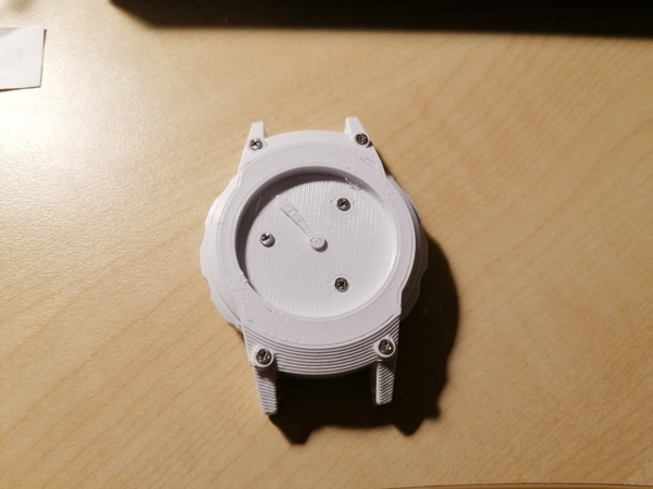
The watch will be about 50mm in diameter, it will only have one hand (the hour hand, obviously), it will be accurate to within 1%, it will probably tick below 10000 beats per hour (very slow for a watch), it will run for almost 12 hours on a single winding, and you'll wind it up and set the time by rotating the outside of the case in the plane of the watch.
Yes, 1% is very poor, almost 15 minutes per day. But I'm not an actual watchmaker, so... lower those expectations.
And, yes, although niche, there is precedent for one-handed watches. And for my purposes it is ideal because the watch isn't going to be accurate enough for minutes to be worth looking at anyway, and I have an ingenious design (if I say so myself) for setting the time that only works if you don't have a minute hand.
I have made a mockup (with no actual works, just ratchets) to show what I mean:
And this is a CAD mockup of a layout for the insides (that I'm not going to use):
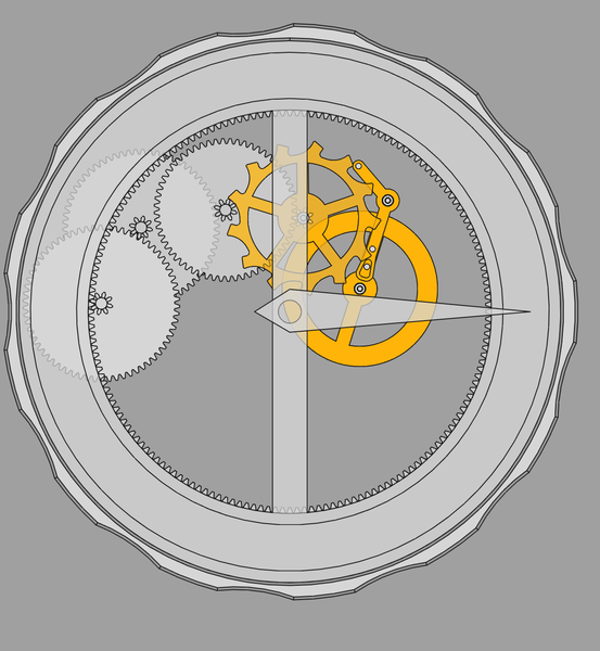
The large circle around the outside is the "barrel" and will contain the coiled up mainspring, which provides the power to drive the watch. You wind it up by rotating the outside clockwise, which coils the mainspring tighter. The mainspring pushes against the inside of the barrel, which has the gear teeth around its inside, which then drives the gear train.
The outer barrel will have a ratchet coupling it to the rest of the movement, so that it is allowed to turn clockwise (when you wind it) but will not be driven backwards by the spring tension.
The hand is mounted directly on the inner part of the barrel. This means the only job of the movement is to slow down the rotation of the barrel so that it completes 1 revolution in 12 hours.
To set the time, you need to turn the outer barrel anticlockwise. This will apply torque to the entire movement, through the ratchet that is preventing the outer barrel from unwinding. The movement itself is held into the case of the watch with a second ratchet, which allows it to turn anticlockwise only.
I think this is quite an elegant solution for a one-handed watch. We don't need any actual mechanism to allow the setting of the hand, because we just rotate the entire movement until the hand shows the right time!
The main caveat is that you need the movement to be held in the case with quite a fine ratchet, because you can only set the time as precisely as you can rotate the movement.
The real problem in making a watch is making an escapement. If you can make an adequate escapement, the rest of the watch will make itself. (Or so I tell myself).
One of the biggest accuracy problems in a watch is that the torque from the mainspring reduces as the spring unwinds. This means your escapement needs to be very good, compared to what you could get away with in a weight-driven clock for example.
Fusee
One historical technique is to use a coned pulley called a fusee so that the leverage of the spring is increased as its pulling force is decreased, to cancel out the effect.
(image from Wikipedia)
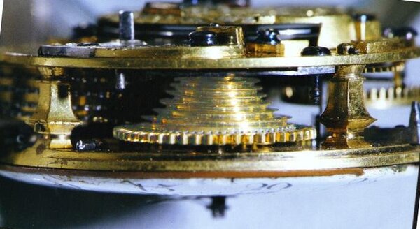
I don't want to use a fusee. It is bulky and difficult to make, and it becomes unnecessary if the escapement is good enough. The only reason they were used in the olden days is because they didn't have better ideas on how to make escapements.
My simple escapements
My first attempts at making escapements were essentially planar analogues of the verge escapement used in historical clocks and watches. (Incidentally, if you want to see a verge escapement operating, you should visit the clock at Salisbury Cathedral, it is thought to have been made around 1386 and is still running today, albeit with some parts remanufactured in the 1900s).
I wrote an escapement simulator to help me come up with escapements that might plausibly work. Just laying out the geometry of the escapement is a lot harder than it sounds, it is very easy to make designs that jam up, or don't provide any impulse to the balance.
Here's an example of the sort of thing I was hoping to use:
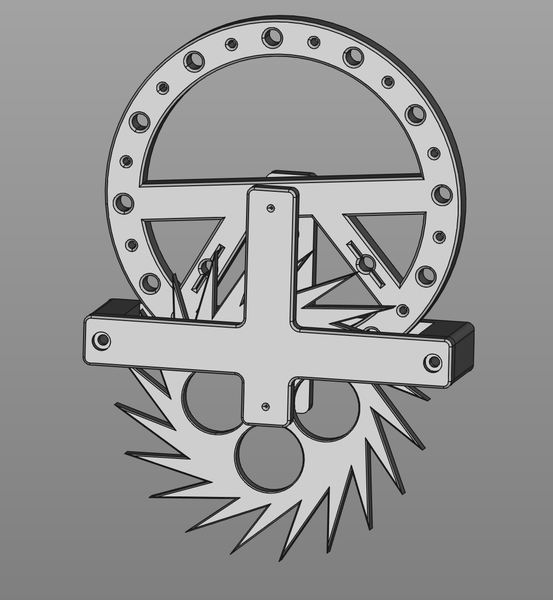
It has 2 pins on the balance wheel, and the escape wheel teeth hit these pins to alternately push the balance wheel back and forth.
This is a very poor escapement because the tick rate changes too much as the drive torque changes. This is because the rate at which the balance wheel accelerates and decelerates purely comes from the escape wheel. An improvement is to add a balance spring, but I spent quite a lot of time experimenting with this sort of thing and I still couldn't work out how to make it accurate enough to work without a fusee.
Lever escapement
So then I moved on to trying to make a simplified version of the lever escapement.
(image from Wikipedia)
The (Swiss) lever escapement is the standard escapement used in almost all mechanical watches for the last 100 years or more, however it has quite a lot of features that need to be formed very precisely in order for it to work correctly.
Pin-pallet escapement
In 1867, someone called Georges Frederic Roskopf invented the pin-pallet escapement as a way to produce lever escapements more cheaply, to use in his "proletarian watch", the first commercially-produced watch for the working classes. You can read more about this watch in History and Design of the Roskopf Watch (mirrored), originally by Eugene Buffat in 1914, translated to English by Richard Watkins in 2007. I first learnt of it from videos by Jacques Favre.
(image from the Watkins PDF)
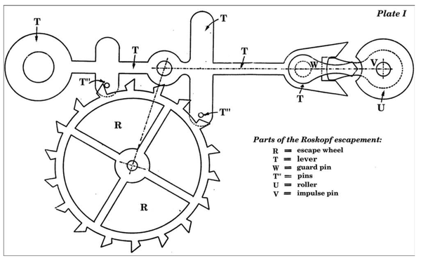
The pin-pallet escapement is essentially the same as a lever escapement, except that the pallet jewels and impulse jewel are replaced with steel pins. This suits me because I can cut steel pins to length, but I can't (yet!) grind jewels to precise shapes.
However the pin-pallet escapement still has a complicated "guard" arrangement (to the right in the diagram). In normal operation none of the guard surfaces touch each other, so it is tempting to omit them. The issue is that if the watch is shaken, then the lever can unlock from the escape wheel and get "banked" the wrong side of the impulse pin, causing the watch to slam to a halt when the impulse pin swings back a fraction of a second later. The guard pin prevents the lever from moving except when it is lined up with the impulse pin.
Captive lever escapement
My idea was to make the impulse pin captive in the lever. This way even if the watch is shaken and the escapement unlocks prematurely, the lever can never get the wrong side of the pin. My first design with a lever was something like this:

And it worked, to an extent. It was a marked improvement over my previous designs because it allowed an increase in amplitude (e.g. 10° of lever movement are amplified to 40° of balance wheel movement), but it has 2 significant drawbacks compared to a real lever escapement:
- it does not allow the balance wheel to detach from the lever
- it does not support amplitudes over 180°
Having the escapement "lock" and allow the balance wheel to swing free from the lever is what allows the balance wheel to keep good time, free from the influence of the drive torque from the escape wheel. And the more amplitude your balance wheel can have, the more time it spends detached, and the less influence the drive torque has on the tick rate.
My design did not support amplitudes over 180° because to do so would cause the lever to pass through the shaft of the balance wheel (yes, we're on shaft passers again). But I persisted with it, because it was better than any of my other ideas.
I added a locking feature to the escape wheel, and this gave another marked improvement in accuracy, enough to convince me that the watch might work, and I set about building a metal version at final watch scale. I've kind of been working on this metal model on and off for almost 2 months now and I still haven't finished it, but this is what I have at the moment:
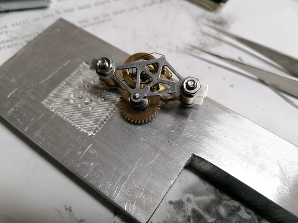
There is a barrel to wrap a tiny thread around, connected to a gear that will drive the escape wheel, and there is a tiny pallet fork with 0.5mm pallet pins, connected to the balance wheel that has a (very poor) homemade hairspring.
And then one day I had the idea that instead of making all the shafts the same length, I could make the shaft that holds the balance wheel shorter, and let the lever arm pass over the end of the shaft, like this:
Making plates at different heights is a relatively standard idea in watchmaking (a plate that is only supported on one end is called a "cock", so this is a "balance cock"), it just took a mental leap for me to actually perceive that it was something that I could apply. I had been labouring under the misapprehension that for simplicity I needed all of my parts to be pivoted into the same plates.
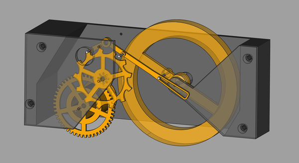
I made some minor improvements to the pallet and escape wheel geometry, and mainly to the shape of the slot to make the impulse pin more free, and this is my current best escapement model:
It shows amplitudes of well over 180°! Great success. And the tick rate hardly varies even as the amount of drive torque changes by a factor of 4 (from 1 to 4 "nuts" here):
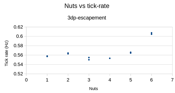
(Note that in the 5 and 6 nut cases, the amplitude was so high that the impulse pin was hitting the balance cock and bouncing back, so the rate increased).
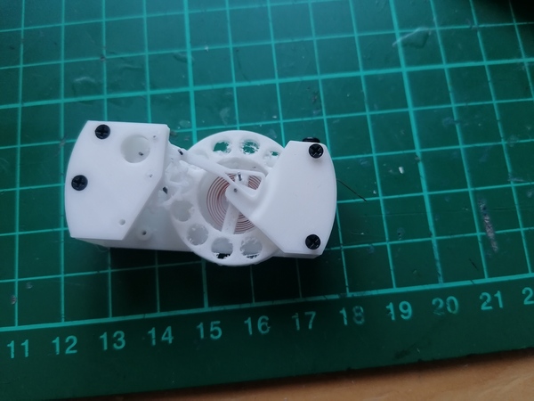
This model was at about 3x the largest scale that I think might fit inside a 50mm watch. Around this time I was experimenting with using a 0.25mm nozzle to 3d print small parts, so I tried to 3d print a version of this escapement at 1x scale.
I have this, which is not quite working yet (the hairspring is from an assortment of clock hairsprings I bought, I didn't wind this one myself):
So the current status on the watch project is that the 3x-scale 3d-printed escapement works well enough to satisfy me, the 1x-scale 3d-printed escapement doesn't quite work yet, but it feels close, and the 1x-scale metal escapement only needs a few more parts (pinion for the escape wheel, something to hold the hairspring to the frame).
Machining
Since I'm not a real watchmaker, I don't have most of the skills that a watchmaker would use to make watch parts, so I have a lot to learn in that regard. But I'm also not constrained to the techniques that a watchmaker would use. As long as I make working parts, it doesn't matter how they get made.
I have a video clip showing how I made my metal escape wheel. The short version is I used a 0.6mm end mill in my CNC router to machine the shape of the escape wheel onto the end of a brass bar, then parted the finished escape wheel off the bar using the lathe.
Clocks
Surprisingly, the watch project has led to a greater interest in clocks rather than watches. I don't know how much of this is just that clocks are so obviously much easier to make.
I enjoyed visiting the Harrison clocks at Greenwich.
I bought a handful of old clock books from a secondhand bookshop in Dawlish, one of them was "How to make an electric clock" by R. Barnard Way, which suggests a design that I think is called a "Hipp toggle". It uses a pendulum to keep time, but the pendulum is given an electromagnetic kick whenever the amplitude gets too low. But I thought the idea of using mains electricity to kick a pendulum is foolish, when you should be able to use the 50 Hz sine wave to count time directly, so I designed and built a stepper motor clock driven directly off 50 Hz from the wall.
I also experimented with what I call the Scotch Yoke escapement. It has no escape wheel as such, instead the pendulum is driven by a Scotch yoke. It will be a poor timekeeper for the same reason that my first watch escapement designs were poor: the pendulum is never decoupled from the drive torque, so more torque will always make it run faster. And in fact it is even worse because the pendulum in the Scotch Yoke escapement always has the same amplitude. But I kind of want to make a clock with it anyway.