
I recently got to see John Harrison's sea clocks at the Royal Observatory at Greenwich. I recommend visiting if you get the chance. This post is about some of the interesting things I observed.
Longitude
In case you don't already know the story of John Harrison, the short version is this:
In 1714, the British government offered a prize for anyone who could invent a "practical and useful" way to calculate longitude at sea. It was already known that you could do this with a clock (the difference between solar noon on the ship and solar noon at some reference location tells you your longitude difference from the reference location). However it was not known how to make a clock sufficiently accurate onboard a ship, due to the temperature and humidity variations and the movements of the ship. John Harrison solved the problem, although the Board of Longitude didn't like his solution and he had great difficulty collecting the prize money, eventually receiving most of the prize at the age of 80, having spent almost his entire adult life working on the project.
(The ultimate dream for any creative person has to be to find a project that you love working on the way John Harrison loved working on clocks. I'm still searching.)
If you want the long version of the Longitude story, check out some of the resources I link at the bottom of this post.
Materials
There appears to be some porosity in a couple of the brass plates in H1. It's hard to see clearly because the clock is inside a glass cabinet which prohibits close inspection. It could conceivably be some other sort of damage.
But if it is porosity, then that you would use such poor materials in such an important project suggests that high-quality materials were hard to come by in Harrison's time, or were very expensive. Nowadays we simply take for granted that we can buy sheets of metal that don't have voids in the middle!
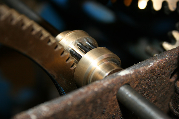
Anti-friction wheels
The wheels you're looking at here are not gears, and they don't drive anything. These are anti-friction wheels, a strange type of bearing.
The clocks use anti-friction wheels for shafts that require particularly low friction. You can read in "Concerning Such Mechanism" (mirrored) that Harrison takes the reduction of sliding friction very seriously. Anti-friction wheels are one method of achieving this.
Instead of having the shaft riding directly in plain bearings, the shaft instead sits on a pair of wheels at each end, and rolls against the wheels, and it is these wheels which ride in plain-bearing pivots. The advantage is that you have geared the rotation down by the ratio of the wheel diameter to the shaft diameter (a ratio of 20 or more) by the time it reaches the plain bearings, with a corresponding reduction in sliding friction.
It looks like there is also a lignum vitae bush that will prevent the shaft from falling off the wheels (if it is shaken too violently for example), but in normal operation the wooden bush will not touch the shaft at all.
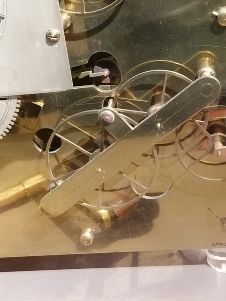
For parts that oscillate, a complicated version of these anti-friction wheels is used, where instead of building the entire anti-friction wheel, only the part that engages the shaft needs to exist.
Maybe in this recording of H2 you can see the movement in the rectangular aperture as the shaft oscillates back and forth:
It's important to remember that the lower long edge of this rectangular aperture (which is actually a large radius rather than a straight line) is the bearing surface of the shaft. It doesn't just happen to touch the shaft, it is what decides where the shaft sits. It bears the weight of the shaft. At each end of the shaft there are two of these. Obviously the foreground one is easiest to see, but you can kind of see one just behind it, at about 90 degrees to the first.
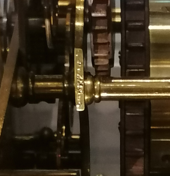
The part that touches the shaft is on the end of a long arm so that the rotation in the arm's pivot is almost nothing.
Here's a picture of the other end of a similar arrangement on H1:
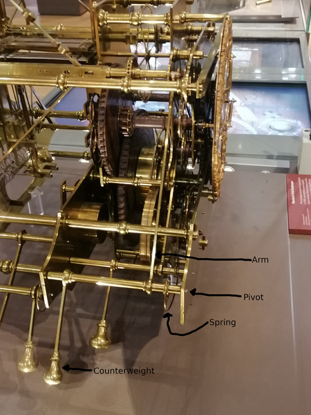
It took me a little while to work out what the knobs are at the bottom of this picture: they're counterweights for these anti-friction wheel-portions. You can imagine that if there wasn't a counterweight then the weight of the portion of wheel that is present will cause itself to fall down.
A counterweight alone is not quite enough, because while it will make the arm stable, it will be stable in any position, so a harsh jolt could still knock it clear of the shaft. For this reason there is also a spring to return the arm to its centre position.
What an enormous amount of work to go to just to create a pivot for a shaft!
Lantern pinions with rollers
A lantern pinion is a type of gear where the teeth are made out of pins suspended between two plates. Here's an example of a "normal" lantern pinion, from Richard's Stuff (not from Harrison):
Not content with the friction properties of an ordinary lantern pinion, John Harrison put lignum vitae rollers on the pins, so that the friction can be further reduced:
Temperature compensation
The temperature compensation mechanisms of the clocks are the hardest part for me to understand. The picture above is from H1. You can see there is a structure similar to that of a gridiron pendulum (also a Harrison invention) lying horizontally near the middle. A gridiron pendulum is designed so that its endpoints remain the same distance apart regardless of thermal expansion, but in this case I expect it is wired up "backwards" so that it expands much more than normal thermal expansion would account for.
The end of the backwards-gridiron presses against a lever which magnifies the expansion further, which then presses against another lever to magnify it even further, a couple of times, until it eventually adjusts the stops for the balance springs. I think the idea is that to prevent the clock from running at a different rate in different temperatures, the balance spring is forced to stop at a different point.
I have no idea how well it works, but it occupies nearly 50% of the volume of the clock, so Harrison obviously thought it important.
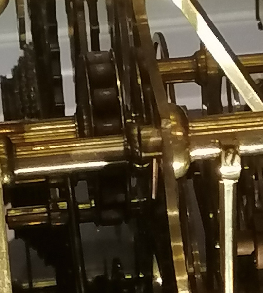
Shaft-passing
There is an interesting feature on H3:
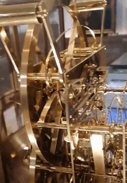
There are stationary pillars that stand in between the spokes of the balance wheels! This is crazy! Why do this?
In the best case it complicates assembly. In the worst case the balance wheel crashes into the pillar.
John Harrison spent 19 years working on this clock, so I guess the answer is just that he did it because he can.
It reminds me of the apocryphal "shaft passer" device, to be specified wherever the spokes of a wheel need to pass through a shaft.
(Incidentally, I also have some thoughts on how a shaft passer should be constructed, and intend to make one one day. See this video with only 2000 views for the best example I've seen so far, although it is not actually a shaft passer per se).
Resources
Some of the best resources for learning about John Harrison, his clocks, and the Longitude problem, include:
- John Harrison and His Timekeepers by Rupert Gould, who restored the clocks in the first half of the 20th Century
- Animations of the Harrison Timekeepers by John Redfern
- Longitude: The True Story of a Lone Genius Who Solved the Greatest Scientific Problem of His Time by Dava Sobel
- The Clock That Changed the World with Adam Hart-Davis
- "Longitude" the dramatic film adaptation
- "Concerning Such Mechanism" (mirrored): a "translation" by David Heskin, of a work by John Harrison
- "Making a wooden grasshopper clock according to John Harrison's principles" by P. Hefetrueb