
I've been working on an oscillating engine simulator. It's a type of steam engine where instead of valve gear, the cylinder swings back and forth, exposing a hole in the cylinder to an inlet port for the power stroke, and to an exhaust port for the exhaust stroke. Very simple. (I've also been working on building one, in the form of a Wig-Wag, but I haven't got very far with that).
You can play with my simulator if you want.
You might enjoy trying to find an engine with the smallest displacement that can provide at least 10 Watts of power at 50 kPa inlet pressure. You'll need to adjust the "load" field to get some useful work out (otherwise the engine will accelerate up to the point that the work done is cancelled out by the losses), but leave the "loss" and "air flow method" fields alone if you want to compare apples to apples. The rest of the parameters are fair game. If you have a go, send me a screenshot of your parameters, and if more than one person bothers then I'll publish a league table next time.

The top group of parameters configures the engine. The bottom group of parameters configures the environment and simulation.
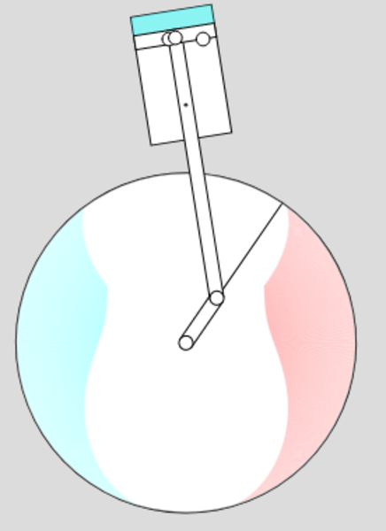
The diagram of the engine includes a representation of the air inside the cylinder, with the colour representing its pressure. The colours drawn on the flywheel indicate the port timing (red means the inlet port is open, blue means the exhaust port is open, and a fatter band means it's open wider).
The plot on the right-hand side of the diagram is a pressure-volume diagram.
It could do with a bit more explanatory text and maybe a better UI, and probably a way to share a link to a set of parameters. And probably some credit to the people whose engine designs & data I have used.
How it works
The rendering is done with p5.js, which is only marginally simpler than using the canvas directly.
The simulation is completely independent of the rendering, which will become important later when I get around to using simulated annealing to produce optimised engines. I hope to be able to improve on many of the published designs.
I'm actually simulating the engine running on compressed air rather than steam. The difference is that with compressed air you don't need to worry (as much!) about the effects of temperature change and condensation, so the simulation assumes the air remains at room temperature.
At every time step, it computes the mass of air that flows through the inlet and exhaust ports (which can be 0, for example when they're closed, or when the pressure in the cylinder matches the pressure on the other side of the port). It computes the volume in the cylinder based on the position of the piston. With the mass of air in the cylinder and the volume known, the pressure can be computed. Knowing the pressure in the cylinder and the cross-sectional area of the bore, you know the force on the piston. Knowing the force on the piston and the effective acting radius of this force on the crank, you know the torque on the crank. Knowing the torque on the crank and the moment of inertia of the flywheel, you can find the angular acceleration of the flywheel, which gives you an updated angular velocity. With the new angular velocity, you can work out how far the crank has rotated during this time step, which also gives you an updated piston position, and then you're ready to start again at the next time step.
There are only 2 real complications: computing the air flow rate, and calibrating the losses.
Air flow rate
I am modelling the ports as a small orifice connecting the cylinder to an infinite volume of either inlet pressure (for the inlet port) or atmospheric pressure (exhaust port). The cross-sectional area of this orifice depends on the area of overlap between the cylinder port and the inlet/exhaust port, and can be further reduced if the piston partially or completely blocks it off.
In the following image the inlet port (left hand one) partially overlaps the cylinder port, but the port is completely blocked off by the piston so there is no air flow. The flywheel is rotating clockwise, which means the piston is travelling down, which means the port is about to be uncovered, as you can see from the approaching red area on the port timing diagram shown on the flywheel.
This orifice-with-infinite-volumes model is not perfectly right, because even if an infinite volume of air were available on each side, the port itself has nonzero length. It's more like a small pipe connecting the cylinder to the infinite volume. It might be interesting to explore how the results from the simulation would change if the port length were taken into account, but I haven't attempted to do so yet. I'm saying that if your inlet suffers a significant pressure drop when air starts flowing through it, then that is an engine construction problem outside the scope of the simulator.
But we still have the problem of actually calculating what the air flow through the orifice should be.
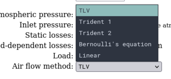
Linear
My first guess was that the flow rate is simply linear in the pressure difference and the cross-sectional area, and then I'd manually find a fudge factor that makes the performance look believable. This is the "Linear" option in the simulator. It actually works surprisingly well, because as long as the engine is running slow enough, the cylinder pressure adapts to the port pressure very quickly, and then there's no flow rate. So as long as your flow rate calculation has high flow at high pressure differences and low flow at low differences, it'll probably work reasonably well. But it's possible to do better, so I sought improvements.
Bernoulli's Equation
My next attempt was from this Stack Exchange answer which says you can use Bernoulli's equation, which (rearranged) says that the velocity of the air through the orifice is proportional to the square root of the pressure difference.
I'm not sure how reasonable this is because every other source on Bernoulli's Equation that I have looked at talks about flows of liquid, not gas. I don't know enough about physics to judge. I also read that air flow can be "choked" when the velocity meets the speed of sound, which means any further change in the pressure difference can not increase the flow rate of the air. I hacked in a hard cut-off at the speed of sound, but it seems unlikely that the change in flow velocity truly stops abruptly once it reaches the speed of sound, so this is also probably wrong.
Trident
Trident Compressed Air Ltd. has a helpful table showing the flow rate of air through orifices of different sizes, and at different pressures.
I assume the data from the table is accurate since they are an engineering company with "Compressed Air" literally in the name. Sadly they don't provide any formulae, so it's hard to extrapolate beyond the range of pressures and orifice sizes given.
I had 2 attempts at manually curve-fitting this data (these are the "Trident 1" and "Trident 2" air flow methods). They are mostly very similar to each other but diverge quite a lot once the pressure difference drops below the minimum from Trident's table.
TLV
My final air flow method comes from TLV's Air Flow Rate through an Orifice calculator.
TLV is apparently a "Steam Specialist Company" (and not of the video game variety) so like Trident they are also likely to have accurate numbers, but unlike Trident they show their working, so once I worked out what all the parameters meant I was able to lift TLV's formulae straight into the simulation.
They also have 2 different formulae based on whether or not the ratio of the pressure difference to the primary pressure exceeds the product of the specific heat ratio factor and the pressure differential ratio factor (whatever that all means), which I think accounts for the flow rate trailing off before reaching the speed of sound.
At some point I will probably remove the "air flow method" option and make it always use TLV.
Losses
I have 2 sources of data on losses.
I emailed Steve Bodiley about the simulator project, to inquire about the piston on his Simple Oscillating Engine covering up the ports as it crosses top dead centre, and he has kindly sent me a spreadsheet of torque measurements from running his engine connected up to a torque brake, which tell me the supply pressure, engine rpm, and torque load for a handful of different conditions.
Secondly, I found this video of a Wig-Wag running with a pressure gauge visible. Given the supply pressure (and finding the engine speed from counting the pulses in the audio track), I can set up the same conditions in the simulator and work out how much load is required in the engine to produce the observed running speed (rpm).
So far the best I've come up with is to say that there is a fixed loss of 0.001 Nm of torque, plus a speed-dependent loss of 2.5*10-5 Nm per rpm (i.e. friction losses increase as speed increases).
This model doesn't fit the observations particularly well, and it is probably the weakest part of the simulator. It would probably benefit both from more data and a better model.
Different types of steam engine
You could simulate a multi-cylinder oscillating engine by simply adding up the torque from each cylinder before applying the update to the crank position.
It would be relatively straightforward to extend the simulator to handle other types of steam engine. I'd need to take out the part that calculates port areas and replace it with something specific to the valving of the different type of engine, and the rest can stay the same.