
I'm working on designing an open source 3D-printable keyboard switch at the moment, with a view to eventually making my own mechanical keyboard using minimal off-the-shelf components (just an Arduino, wire, and diodes, with homemade parts for switches, keycaps, and case). I have not made a keyboard yet, but yesterday I made a device to test how many presses a switch can withstand before it stops working.
Here's a video of it in action:
All the code and CAD is on the github project, so if you happen to want to make one, just follow the instructions in README.md. It's actually not very well designed, so if you can, you should design a better version (in particular, try to position the servo so that it can move through its full range of motion instead of crashing into the frame).
How it works
It uses a servo to turn a robotic finger that slowly presses the switch down. When it detects that the switch has closed, it lights up the LED and waits 100 ms for the contacts to settle, before slowly releasing the switch until it detects that the switch has opened again. At this point it switches off the LED, resets the servo to the start position, and writes the measured activation and deactivation positions to the PC over the USB serial connection. In the event that the servo reaches the configured end point without the switch closing, or reaches the configured start point without the switch opening, it logs a failure instead. If the switch failed to reset, it won't start another cycle until it does.
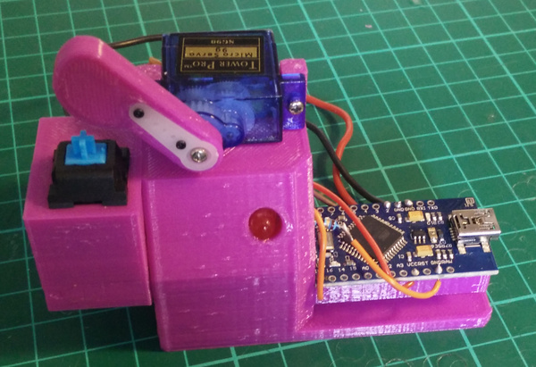
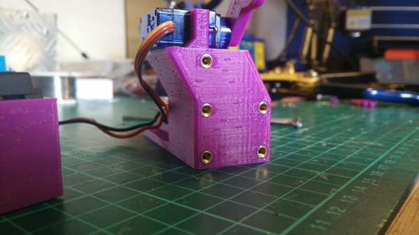
The switch is held in a separate part that is attached to the device with M3 screws. In principle, this makes it easy to make different holders for different types of switch without having to rebuild the entire device. The first one I made fits Cherry MX switches, and here is holding a "kaiche" (?) clone of a Cherry MX blue, which is the same as I used for the clock switch on the automatic chess board. (The tiny writing on the switch says "kaiche" as far as I can tell, but all I can find about this word online is that it is the Chinese verb for "to drive a car").
I've started using PrusaSlicer on the Anycubic i3 Mega, because it seems more maintained than Slic3r (which it is a fork of). In general it produces better quality parts than I ever managed with Slic3r, but I have noticed some strange blobs on the outer surfaces of parts.
I think these are caused by the start/stop position in the layer, but I don't know why they're more pronounced than they used to be.
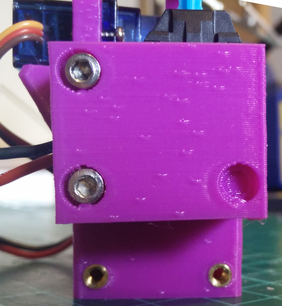
I made a small blunder in the CAD model for the switch holder: one of the screw holes does not have a hole in it! Fortunately 2 screws proved sufficient to hold it securely.
The switch was a very tight fit in the holder, I should have added a hole in the bottom so I can poke something up inside to push it out.
I used an Arduino "Pro Micro" for this project, mainly because I had it lying around already. Normally I'd use a Nano because it's slightly smaller. One advantage of the Pro Micro is that it can act as a USB peripheral, which means I might eventually be able to use it for the actual keyboard.
Lots of the code uses millis() for timing, and I did try to account for it overflowing after 232 ms (or ~49.7 days), but don't know if I succeeded, and realistically will never find out.
I have found the Arduino sometimes spuriously resets itself. I do not know why. My best guess is that the servo draws too much power, which causes a brownout. It worked for about 4 hours continuously yesterday until the first spurious reset, but was doing it every few minutes this morning. Maybe the servo draws more power after it gets warm? If I can't convince myself that the resets are caused by something else, then I'll try adding a separate power supply for the servo. Or maybe just tolerate it.
Speed
A servo is controlled by sending it a PWM signal with the pulse width between 1000 microseconds and 2000 microseconds. The width of the pulse tells the servo which position you want it to hold. The servo can't jump to a given position instantaneously, so once you've requested a movement, it takes some time for the movement to actually happen, and during that time you don't know what position the servo is at. For this reason, it's not enough to just ask the servo to move the finger to the maximum position, we have to move it in small increments so that we always know what position the servo is at at the time the switch closes.
But how slowly do we need to move the servo? I tested a range of different speeds to see how fast I could go before the data became worthless:
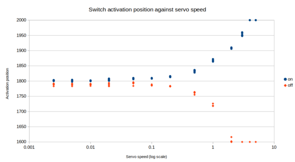
The unit I've measured the servo speed in (x-axis) is "microseconds of pulse width per millisecond". That is, a speed of 1 us/ms allows the width of the pulse in the PWM signal to change by 1 microsecond per millisecond of clock time, which is probably technically a unit-less value. Hope that makes sense.
The y-axis shows the value for the pulse width at which the switch turned on (blue) and off (orange). You can see that as the speed goes up, the detection of the switch turning on or off gets delayed due to the time it takes for the servo to respond to our inputs. It caps out at 1600 and 2000 microsecond pulses because those are the limits to the servo motion that I configured.
I chose 0.2 us/ms for the servo speed because it still gets reasonably useful data, without running unreasonably slowly.
Switch testing
I left it running overnight just to see what sort of data we get. I logged it with "cat /dev/ttyACM0 > log".
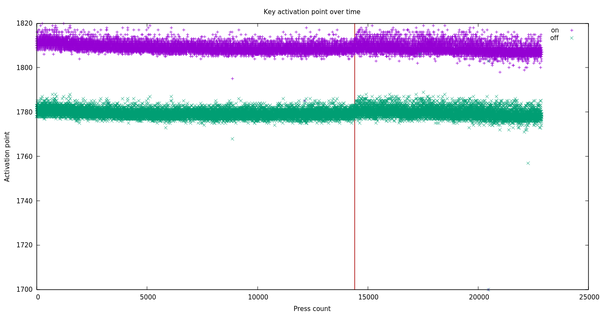
The x-axis is roughly "time", except that the Arduino reset about 4 hours into the test, which killed the USB serial connection, which killed my data collection until I switched it back on this morning. The Arduino resets and continues working after about 1 second, but cat had exited so the data logging did not automatically resume. This point is indicated by the red line on the graph at x=14393. I think we missed about 27,000 presses here, which is a shame but at least I know to watch out for that in the future (i.e. have a program automatically reopen USB serial after it dies, and preferably fix whatever is making the Arduino reset).
You can see that when the logging resumed after the 8 hour gap, the range of activation positions had increased. Sometimes the finger had to press slightly further before activating the switch. I don't know exactly why, but something must have worn in slightly over the course of the test.
I manually triggered 1 failure by holding the switch down after the robotic finger let go, just to make sure it was still detecting failures correctly. Apart from that, across the ~23,000 presses that were logged, there were 0 failures detected, which I suppose is what you'd expect from a commercial product.
To convert between times and press counts, we need to know how long the cycle time is. It actually takes a different amount of time depending on the exact position at which the switch closes and opens, but I counted frames between when the LED switches on from one cycle to the next in my video and found that the average cycle time was 24.5 frames, or about 940 ms. I should add timestamps to the logging for next time.
It's likely that at least some of the change that was measured in this test comes from wear in the servo rather than the switch. That might invalidate any conclusions you might try to draw about commercial switches, but I expect it will not be a problem when I am testing homemade switches. Feroz reckoned my switches would last about 2000 presses before they stop working. If you want to submit your own guess, get in touch and I'll announce a winner once I've found out!
When I filmed the video of the tester (before I started logging the data), you can hear 2 distinct clicks when the switch is pressed. When pressing it by hand I didn't notice this as it's difficult to apply such small precise movements. But as the plunger is pressed almost to the activation point, there's a first click, followed some time later by a second click when the switch actually closes. From the animation of how a Cherry MX blue switch works, I think there should only be 1 click before the switch closes. The click should be audible when the white plastic piece pushes past the bump, allowing the spring contacts to close.
(I did take a "kaiche" switch apart and verified that it works the same way as a Cherry MX).
And interestingly, after the 50,000 or so presses that my device has performed, the first click is now gone! I think some piece of plastic must have been snagging, but has now worn down and the switch works more like how it's supposed to.
Other people's 3D-printed switches
The only other person I've come across working on 3D-printed keyboard switches is Riskable 3D Printing on YouTube. He is somewhat further along than me, and his approach is slightly different. While I'm dead set on implementing the contacts inside the switch I design, Riskable 3D is more interested in making a high-quality switch regardless of off-the-shelf component usage, and seems to be planning to use magnets and reed switches to sense when the switch has been pressed. An interesting project nonetheless, although doesn't appear to have had any updates in the last couple of months.