
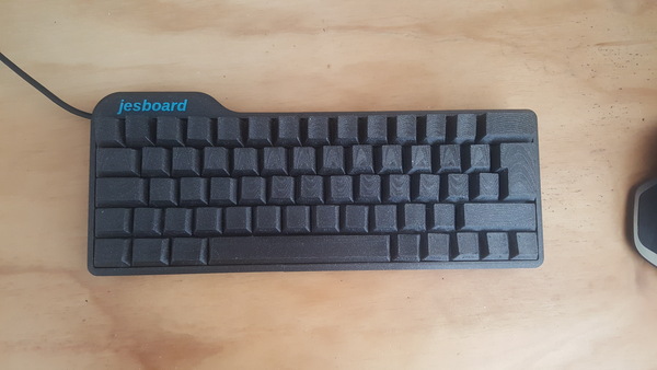
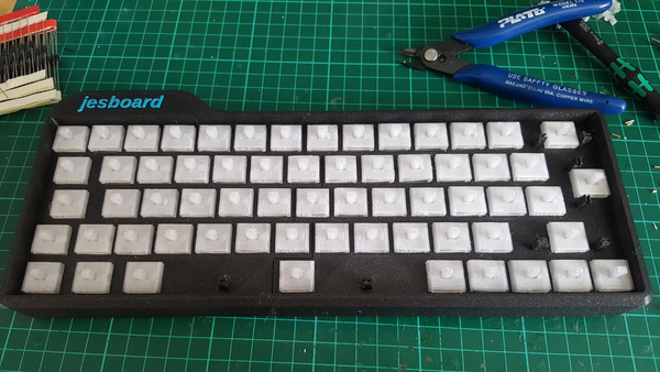
The keyboard is done! This is basically the result of what I've been working on for the past 2 months, which has involved 3 iterations of testing machines, over 100 printed switches, and now finally a keyboard that I can type on. Unfortunately it is not a very good keyboard, but you can't win them all.
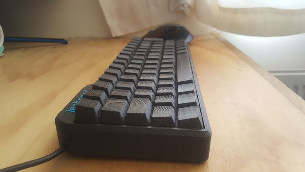
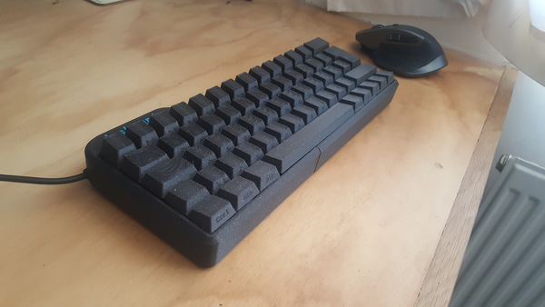
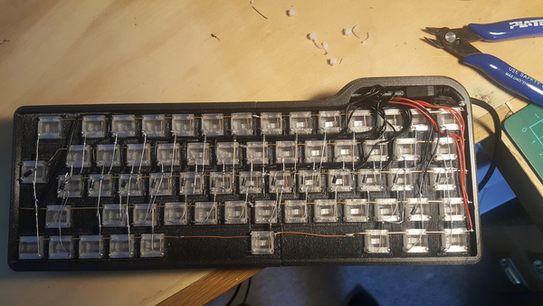
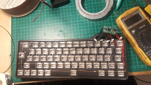
Here's some pictures of the keyboard:
And here's a video of me typing on it:
(In the video it is a bit wobbly because the back is propped up to take the pressure off the exposed wiring. I have subsequently printed a couple of small legs to raise up the back of the keyboard and now it is a lot less wobbly, but it could still do with some soft feet).
I am very happy with how the keyboard looks, and also happy that I have managed to produce a working keyboard using 3d-printed switches in the first place. I believe this may be a world first.
That said, I started using the jesboard to write this blog post, and it was too annoying to type on so I went back to the Filco. Spending some time typing on my homemade switches has given me a newfound appreciation for just how good Cherry MX switches are. I'm not sure what it is that makes the jesboard so unpleasant to type on, there's just a general vagueness to it that makes typing frustrating. Pressing a single key up and down feels basically fine, which is why I hadn't noticed this problem while developing the switches. But trying to use it as an actual keyboard, and type at a sensible speed, just feels really bad. It is genuinely the worst keyboard I have ever used. So that's disappointing.
I think to improve upon this you'd probably want to reduce the activation force (that's easy, just make the spring thinner) and add some tactile feedback so it is easier to tell when the switch has actually been pressed. Beyond that, I'm not sure.
Switches
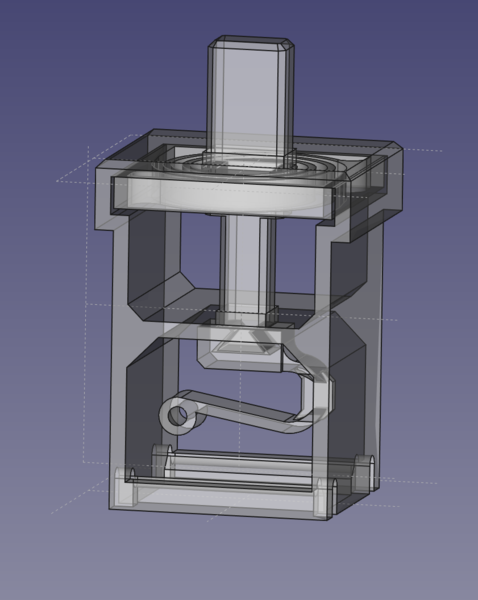
If you want to learn more about the switches, I would recommend looking at some of my other posts tagged "keyboard", but in short: pressing on the stem at the top compresses the spiral spring (I copied the spring design from Riskable 3D Printing, he is also developing 3d-printable keyboard switches, but using magnet sensors instead of making mechanical switches himself). Once the stem is pressed down far enough, a contact wire bridges the 2 contacts at the bottom, activating the switch. As the switch is pressed further, the leaf spring compresses, allowing the stem to move further down while allowing the contact wire to remain in place. Eventually the spiral spring bottoms out against its casing and then stem movement stops. When the key is released, the spiral spring pushes everything back up to the top.
The leaf spring has a section in its bend that is narrow in the "other" axis, to allow it to easily tilt side-to-side to ensure good contact with both of the contact wires.
I don't have a good photo of the latest switch design, but I have this of an earlier version:
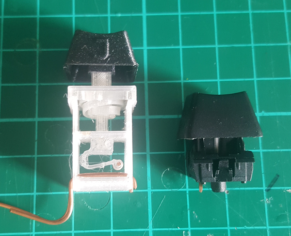
The working principle is the same but the new version is a bit shorter.
The switches are printed in PETG. If you want to see them in action, you might enjoy my video of operating the switch tester. The final incarnation of the switch design lasted over 350k presses in all cases, and some instances still hadn't failed at 500k presses. This is a lot lower than the "tens of millions" that might be expected of a commercial switch, but it's a big improvement over 13907 which is where the first iteration failed, and that was on an extremely gentle machine.
I said I was going to experiment with moving the activation point down to 75% of the plunger travel so as to reduce the strain on the leaf spring. I did test this on the new machine, with 5 of the old design and 5 of the new design side-by-side, and the new design lasted almost twice as long, so that was a good improvement.
The gold-plated "jewellery wire" that I bought off eBay ended up working well and soldering well (so I conclude it was not varnished), and 4 metres (costing £4) was just enough to do the entire keyboard.
If you want, you can download the switch CAD, including STL and FreeCAD files.
Case
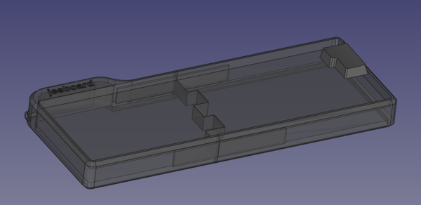
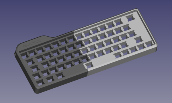
The case is split into 2 halves that are then glued together, so that it fits on the bed of the 3D printer. There is a large rectangular hole at the top and bottom in each half, and a long bit of plastic inside joining them, to add a bit more strength to the joint. There's not a lot to the case design really, it is just a shape to fit the switches into, with a bulge at the top to house the microcontroller, an exit hole for the cable, stabiliser mounts, and a cool-looking logo. I made the general shape of the case halves in FreeCAD, and then imported the resulting STL into OpenSCAD to cut out the holes for the switches, because I found it easier to get the layout correct with code.
I printed the logo in a different colour by having the printer stop and wait for me to change the filament at the layer height where the colour changes, using the M600 G-code command. PrusaSlicer has a nice GUI for setting this up, so I didn't even need to manually edit the G-code.
If I were to make another keyboard, I would give myself more space to work with underneath by reducing the thickness of the "solid" middle part that the switches are mounted in. I found that there was not really enough room to run the diodes and wires. I would also add provision for a few screws to attach a bottom cover to protect the wiring inside.
The case and keycaps are printed in Prusament Galaxy Black PLA, which I think gives a really nice finish.
Keycaps
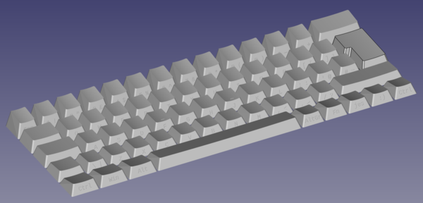
The keycaps were designed using KeyV2, a free parametric keycap library for OpenSCAD. If you want to design some keycaps, you should check out KeyV2. Its creator, Bob, is friendly and gave me helpful advice and assistance.
There are several different ways to make an ISO (UK-style) enter key in KeyV2, but I couldn't find any combination of settings that would let me have rounded corners, sloping top, and dished top, so I ended up making the enter key by hand in FreeCAD.
I was originally going to use "outset" legends on the keycaps, like I used on the macro keypad. But I read this comment in the KeyV2 source which changed my mind, so I used inset legends instead:
// make legends outset instead of inset.
// broken off from artisan support since who wants outset legends?
$outset_legends = false;
But having printed all the keycaps, I'm not sure whether I think inset legends actually are better. They range from "perfectly fine" to "almost invisible" depending on the lighting. I'd say the outset legends were easier to read.
Wiring
The switches are hand-wired in a 15x5 keyboard matrix, with diodes allowing current to pass only in one direction. 14x5 would be enough if you thought about it a bit more than I did, but 15x5 is fine.
Originally I was planning to use an Arduino for the microcontroller, which has only 16 IO pins. This would allow for an 8x8 matrix, but when I went to layout the wiring, I came up with this, where red is columns and green is rows:
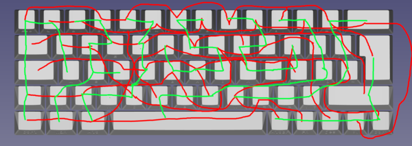
Obviously this is too complicated to wire up in real life, particularly in the small amount of space provided in the bottom of my case. You may also notice it was too complicated for me to lay out in GIMP, as I have failed to connect the full-stop and apostrophe keys to any row. For these reasons I decided to use a Teensy 2.0 instead, which allowed me to use a more sensible matrix layout:
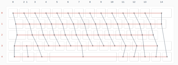
(I laid this out on kbfirmware.com).
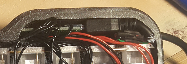
The other part of the wiring is that the USB cable has to reach the microcontroller. I left a 4mm hole in the side of the case for the cable to run through, but this is too small for the connector on the end. I was originally planning to cut the connector off and solder the wires directly to the USB pads on the micocontroller board, but they were too small and annoying to access, so instead I just soldered the MiniUSB end back on and plugged it in. It's a tight fit but it does the job.
In hindsight, I am not sure whether I regret hand-wiring the keyboard. I toyed with the idea of getting a PCB made up that I could directly solder my switches to. It would certainly have made it easier to put the keyboard together, but I thought outsourcing the manufacturing of a PCB kind of takes the edge off making your own switches...
Stabilisers
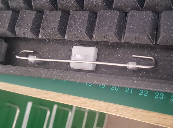
Here's a clip showing how the stabilisers work:
The idea is that when you press down on one side you cause the bar to rotate, which then pulls down on the other side of the switch, forcing the key to move down parallel (instead of rocking) and activate the switch properly. The bar is made of 1.75mm stainless steel wire bent into a suitable shape. Thick stainless wire is quite hard to cut, but doable with a big-ish pair of nippers.
While trying to fit the stabilisers for the spacebar, I managed to break off the mounts attached to the case. This is bad news because the case halves are about a 10-hour print each, and aside from that I had already soldered up all of the switches. To reprint the case halves would involve undoing all of my soldering work, and then 20 hours of printing, and then redoing all of the soldering.
I wasn't interested in redoing all of that work, so as a last resort I drilled a hole into the case in the position of each stabiliser mount, and printed 2 new stabiliser mounts, long enough to fit in the holes. I printed the mounts in PETG so that they'd be less likely to break.
This worked really well, disaster averted! The mounts were a tight fit in the drilled holes so I didn't even need to use any glue.
QMK
I used QMK for the keyboard firmware, running on a Teensy 2.0. I found it quite hard to get started with my custom keyboard, because almost all of the documentation is geared towards the case where you are using an off-the-shelf keyboard which is already defined in QMK. The key point I needed to know was that you can use the script "./util/new_keyboard.sh" to create a new keyboard, and I found the AVR Processors page of the QMK documentation to be most helpful. The process is something like:
- Clone the QMK repo:
git clone https://github.com/qmk/qmk_firmware - Install the QMK tool from PIP:
sudo python3 -m pip install qmk - Setup QMK:
qmk setup - Install the Teensy loader program:
sudo apt install teensy-loader-cli - Create a new keyboard:
./util/new_keyboard.sh - Edit ./keyboards/your-keyboard-name/config.h to configure your matrix dimensions and IO pins
- Edit ./keyboards/your-keyboard-name/keymaps/default/keymap.c and configure your keymap. This is the hardest but most fun part. I looked at some keymaps of other 60% keyboards to see how you're meant to do it.
- Compile your firmware:
qmk compile -kb your-keyboard-name -km default - Flash the firmware to the Teensy:
The "-w" means it will wait until the Teensy is reset, so once you've entered that, hit the reset button on the Teensy and wait a few seconds, and you're done!teensy_loader_cli --mcu=TEENSY2 your-keyboard-name_default.hex -w
Conclusion
Apart from the fact that the keyboard is quite unpleasant to type on, I'd say this project was mostly a success. I enjoyed the process of developing the switches, but although there is obviously more work that could be done, I think I've had quite enough of it. I think my mistake was optimising for reliability instead of feel. If you want to work on 3d-printed switches, I would suggest focusing primarily on the switch feel, and only optimise for reliability once you have switches that feel good to type on.