
In this post I'm going to explain what a Douzieme gauge is, show you how I made one myself, and propose some alternative designs for higher precision.
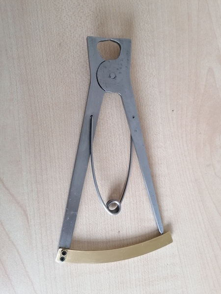
Mine looks like this:
What is a Douzieme gauge?
"Douzieme" is a French word meaning "one twelfth". As a historical unit, the Douzieme refers to 1/12 of a ligne, which is about 2.256mm. Apparently the "ligne" is still used in French and Swiss watchmaking.
A Douzieme gauge is a traditional watchmaker's measuring tool. Here's a picture I found online:
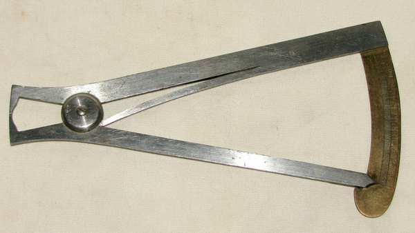
The legs are squeezed together by hand (against the spring pressure), which opens the jaws. The jaws are placed around the object to be measured, and then the legs are released, allowing the spring to push the legs back open, making the jaws close. When the jaws close around the object, the dimension can be read off the scale. The scale is (say) 5x as far away from the pivot as the jaws are, so the length at the jaw is amplified by a factor of 5 at the scale, which is how the device achieves its precision.
What a simple and ingenious idea! This inspired me to make one for myself.
Making a Douzieme gauge
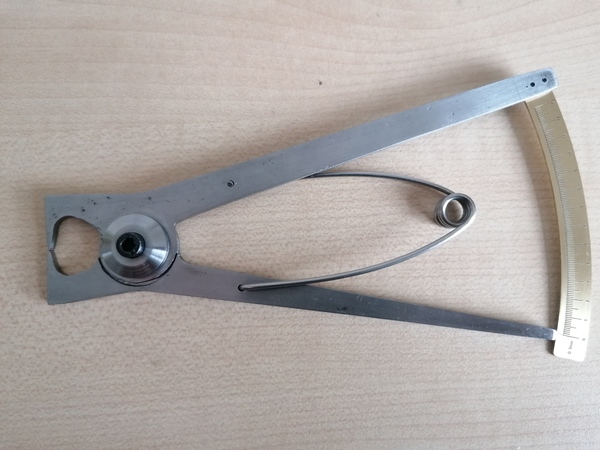
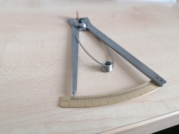
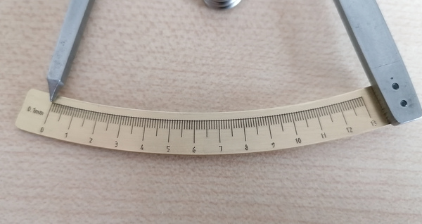
I made this one:
Pictured here measuring the thickness of a watch gear at 0.55mm.
I don't actually work in douziemes, so I graduated the scale in 0.1mm increments (which are 0.5mm apart in reality, because of the 5:1 ratio).
I opted to make the spring out of stainless steel wire, instead of integrating it into one of the parts, because I made my parts out of mild steel and mild steel springs don't work very well. (For that matter, mild steel jaws probably won't work very well, but I have a solution for that).
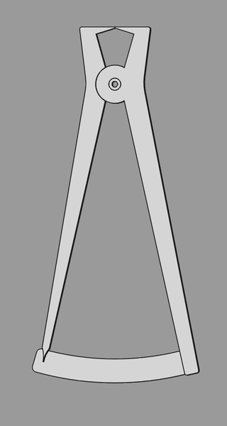
I started by designing this in FreeCAD:
I made both of the main parts out of 3mm mild steel sheet:
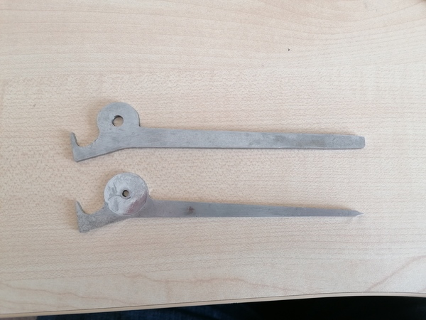
One of them was made on the CNC milling machine, and one was made by hand on the bandsaw, because I wanted to compare how long each process took. It was 47 minutes for the CNC part and only 26 for the one I did by hand, but I had very suboptimal cutting on the milling machine, and the one I did by hand is less faithful to the intended dimensions and needed more cleaning up with files, so it's swings and roundabouts really.
And I did use the milling machine, even on the handmade part, to cut the step around the pivot. This is the clamping setup I used:
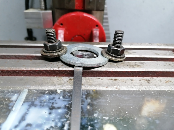
Not great but it was adequate. I should really get a strap clamp set.
I also made a clamping washer on the lathe, and shortened an M4 allen screw to hold the parts together at the pivot.
Then I came to making the spring. My first thought was to make a simple bend in the stainless steel wire and put some holes in the sides of the legs to accept it, but it became obvious that that wasn't going to work (the spring would rotate freely instead of lying in the plane of the tool).
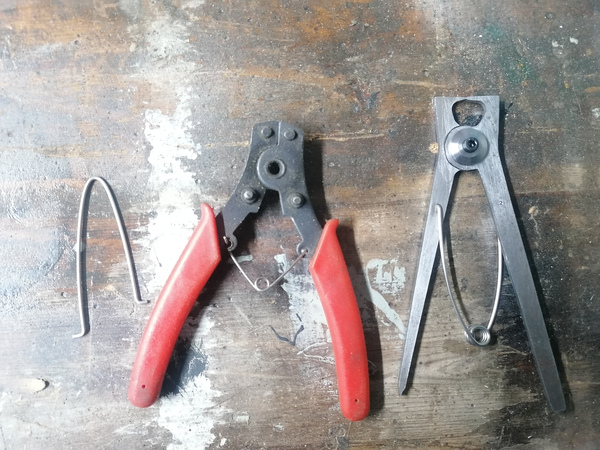
So instead I copied the design from a pair of circlip pliers. I wrapped the stainless steel wire around a screwdriver a few times to form the coil, and hammered the ends over in the vice to make the ends. It works surprisingly well.
I cut out the shape for the scale according to the CAD model, but realised it was not going to work because it is too short:
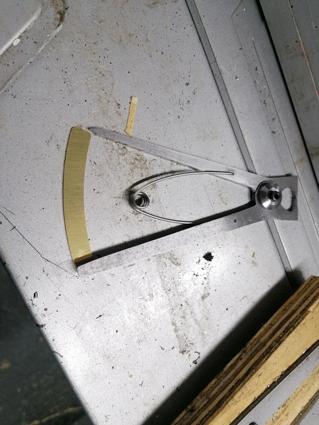
The pointer is off the end of the scale.
I think probably one of the pieces ended up with the jaw slightly shorter than intended, which means the jaws close closer together, which means the legs end up further apart.
So instead I made a series of paper scales, designed in LibreCAD, to get the perfect alignment:
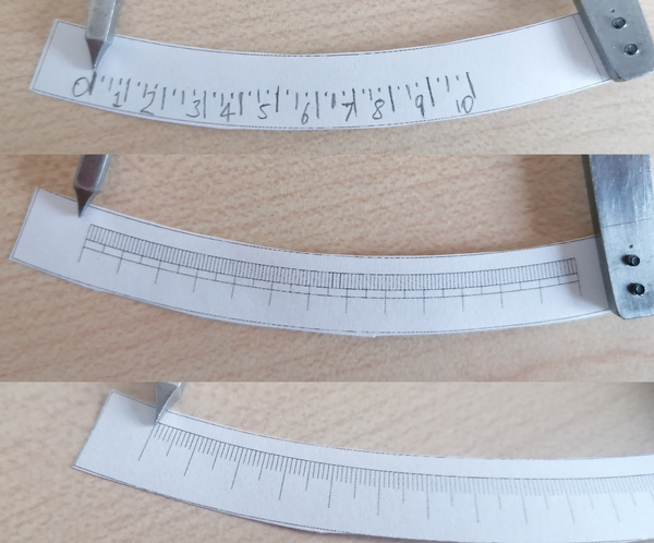
It is definitely worth going through several paper iterations to make sure the scale is correct.
I found making the scale in LibreCAD to be very laborious, and then I found that LibreCAD doesn't even have any CAM capabilities, despite the homepage stating that "LibreCAD started as a project to build CAM capabilities into the community version of QCad" - it seems it still doesn't have any. It also does not have a constraint solver and is not parametric, it feels like a big step back compared to using the Sketcher workbench in FreeCAD.
If I were going to make another scale like this I would probably write a Perl script to make an SVG file instead.
Once I had a design I was happy with, I made the scale using a diamond drag engraver on the CNC router:
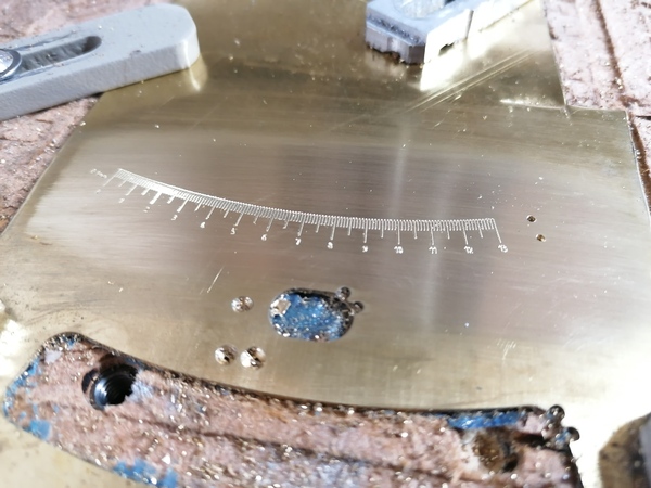
With the engraving filled in with black paint and then sanded back.
And I made a tiny brass clamping piece to hold the scale on with 2x M1.6 countersunk screws:
Why the clamping piece? Why not just countersink the holes in the scale? I made the holes in the scale slightly oversized to allow for positioning adjustment, but if the holes were countersunk this wouldn't work.
The capability for repositioning the scale is my solution for when the jaws wear out: I can file the jaws flat again, and move the scale!
The writing on the scale is very small and some of the digits are distorted (in particular the "8") because of flex in my CNC router. But it is readable.
I am very pleased with my Douzieme gauge, I have built it to a much higher standard than I usually manage.
Line spacing
If you design one of these, then you should take note that the lines on the scale should not strictly be spaced at equal angles, because what you are really measuring is the chord length rather than the arc length. However the error if you space them at equal angles is so small that you can probably ignore it. I did go to the trouble of spacing them correctly the first time, but then realised I had messed up the alignment and couldn't be bothered doing the several-hundred clicks in LibreCAD to rescue it, so I started again and went with equal angles. Maybe if you are better at LibreCAD than me you could do it properly.
Alternative designs
Vernier Douzieme gauge
Instead of just having a pointer on the "moving leg", we could put a Vernier scale on it. That way we'd read the scale with the same precision as a normal Vernier caliper, except the scale is amplified by 5x compared to the object we're measuring, so we'd get 5x the measuring precision of a normal Vernier caliper.
Micrometer Douzieme gauge
Another idea is that instead of the legs being spring-loaded and moved by hand, they could be moved by a screw, and we can read off the length at the legs with a micrometer scale, which again gives us 5x the precision of the micrometer because of the leverage.