
Since breaking the last switch, I re-printed the same design in PETG to see if it would last any longer, and it did! It reached over 100,000 presses under the gentle testing regime without showing any failures, a big improvement over failing at 13,907.
Harder testing
The first tester was extremely gentle on the switches. Much more gentle than any human typist.
I stopped it after 100,000 presses and modified the Arduino program so that instead of letting go as soon as it detected that the switch had contacted, it would instead press the switch all the way to the bottom of the stroke every time, and then measure whether it was successfully contacted. I found that it started to fail after about 6,000 of the hard presses:
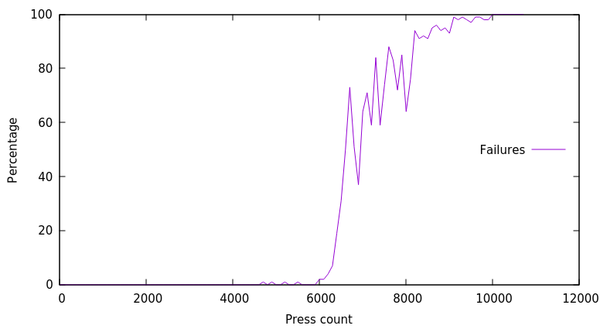
Failure rate rose from 0% to 100% between the 6,000th and 10,000th hard press. The switch was actually still contacting successfully as it was pressed down, but then as the plunger reached the bottom of the stroke, the conductive copper tape was being levered up and away from the contacts, which was breaking the circuit. This problem would not have been discovered if I had just left it at gentle presses.
Here's an illustration of what's going on at the contacts of the switch:
The red light shows when the two contacts are bridged together by the copper strip. Right at the bottom of the stroke, the red light goes out because the copper strip is levered up and away from the contacts.
I don't know why this only became a problem after 6,000 presses (or, 106,000, including gentle ones). I expect it was just on the cusp of becoming a problem all along, and the copper strip got bent up over time.
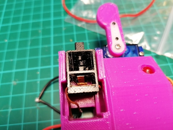
Here's a picture of the PETG switch in the tester, showing the copper strip at the bottom. Unfortunately it's hard to see much inside the switch because it is black and shadowed:
New tester
Using the servo to press a finger on the switch is the easy way to do it, but for improved speed we would want a spinning cam pressing down on the switch. The reason I didn't do this at first is because I thought we might miss failed presses on the switch (e.g. if the motor does a complete revolution without pressing the switch, how would the Arduino know whether it missed one or not?), and we might not notice if the activation position drifts over time. Stavros suggested putting a small hole in the cam, shining an LED at the cam, and sensing each rotation by detecting when the light reaches a photoresistor on the other side. This is a great idea, because then we get a very precise measurement of the motor RPM, we never miss a single revolution, and we can detect what position the switch activates at by measuring the time between the start of the revolution and the switch activating.
LEDs and photoresistors seem a bit primitive to me, so I used a magnet and a hall effect sensor, but it's the same principle.
Here's a clip of the new tester, with one of the "kaiche" Cherry MX clone switches:
(The wiring is a mess but it seems to work OK for now).
I have provision here for 6 testing modules to be running simultaneously, off just the 1 microcontroller, before I run out of I/O pins. The motor has a switch on it so that I can disable an individual motor and hot-swap the switch without interrupting the other tests. (I doubt I'll ever want to test 6 at once, but 2 at a time might be handy). The motor speed is controlled by adjusting the duty cycle of a PWM signal which controls the L298N motor driver. In the video I was using a PID controller to try to target a precise motor RPM, but tuning it proved inconvenient so I am now just using a fixed duty cycle.
The new tester records the estimated rotation position of each time the switch turns on/off (based on timing - i.e. if the rotation takes 200ms and the switch comes on 50ms after the rotation started, then that's 25% into the rotation). A quick test of the commercial switch looked like this:
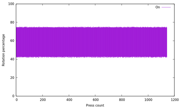
Essentially, as the motor sweeps through a revolution, we are sweeping up the y-axis from 0% to 100%, and whenever the switch is "on" we plot a purple mark, and whenever the switch is off we don't. You can see that the switch comes on at about 42% into the rotation, and goes off at about 75%. This in contrast to the homemade PETG switch, after being broken by the "hard presses":
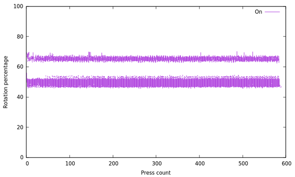
It comes on at about 47%, then goes off again at about 52%, then comes on at 63%, then goes off again at 68%. This is a great way to visualise problems with the switch.
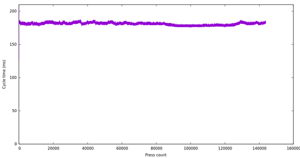
Also, the old tester topped out at about 1 Hz for reasonable data, where the new tester can range from 2.8 Hz to 7.7 Hz depending on the PWM duty cycle. The motor speed did vary a bit over time, so a PID controller might have been handy if properly tuned:
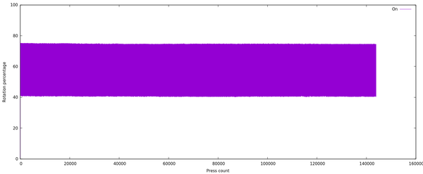
But the detected on/off times of the switch seem to be relatively speed-invariant (as you'd expect):
Compared to the old tester, this is much better data, gathered much more quickly. It's an improvement all around, except for how noisy it is. Last night I put a bucket over it and then put a dressing gown over the bucket to try and keep the noise down, which worked quite well.
Being able to automatically test the switches is great, because it quickly identifies problems to solve. If we were able to automatically test the mower, maybe that would have been more reliable during races. Feroz suggested sticking some turf to a treadmill, but I think only as a joke.
Switch improvements
For the next attempt, I want to make the following improvements to the switch design:
- I should remove as much plastic as possible in between the copper wire contacts, to solve the problem of the copper strip getting levered up and breaking contact
- currently the coil spring is mounted in a kind of pointlessly-tall 3-walled box that is wedged inside the housing, it should instead have a slim 4-walled box that slides into a "shelf" in the housing
- the spring only has 1 coil at the moment, which means the forces are not balanced and it pulls off to one side as it is stretched; I want to have 2 nested coils attached at opposite sides so that the forces balance and it self-centres
- Stavros said that his printer left the coil only barely attached to its pointlessly-tall box, I should fillet the join so there is more material there
- the switch body is 2mm taller than necessary, as the plunger can never fully reach the bottom, I should just knock 2mm off
- the plunger is a tight fit in its hole and requires manually cleaning up with a knife, I should increase the clearance
- I should dry out my PETG a bit more, I left it in the oven for an hour at 60°C and the quality improved a lot, but I think there is more moisture to drive out
- the bottom of the switch should be a bit narrower so that it fits in a 14mm square hole even with the wires poking out the side, i.e. provide clearance for the wires
Longer-term improvements would include:
- figure out how to use a coil spring to implement the flexible copper strip, it will probably be more reliable than a flat plate
- figure out how to add a clicky tactile bump to the activation force, instead of just a linear spring
I think that's all! As soon as I've got something that can last a sensible number of cycles in the new tester, the next step is to build a 4-switch "macro keypad" and see how it feels to actually use. I'm considering using the Arduino Keyboard library on an Arduino Pro Micro, but it might be easier to just use QMK and not write any of the firmware.