Last modified: 2025-11-16 16:02:30
< 2025-11-15 2025-11-18 >I've worked out how to do this.
Imagine a heliocentric orrery that just has the sun and the earth.
You have a model of the sun in the centre, and let's say a ring gear around the outside.
The earth assembly has a motor that drives it around this ring gear, this motor's axis is parallel to the ecliptic axis.
So that motor drives the assembly around the sun once per year.
And then on top of the assembly you have another motor whose axis is inclined by 23.44°, and this one rotates ~once per day.
So if you reorient things in your mind so that the earth is fixed in place, you then want the first motor to be fixed in place to the earth and its shaft parallel to the earth's axis. And this rotates an assembly which has a second motor inclined by 23.44°, and this second motor only turns once per year.
I might be able to get away with not using any gear reduction for the 2 main axes (obviously 254:19 for the moon axis).
And then are we faffing about with these magnetic encoders, or finding some sort of motor that doesn't lose steps when powered off?
Actually, even knowing the motor position isn't quite enough, because you need the moon axis to be in sync with the sun axis. That may be fine though, just manually shift the moon if it gets obviously out of sync. It's unlikely that you'd have a powercut longer than a year, and if you do it's not too much trouble to resync the moon once you switch it back on.
Meh, I guess the magnetic encoders really are the best option. Will obviously need slip rings to get power to the second axis - perhaps the easiest way is to just use 2 wires of slip rings, to supply power, and then have both motors in that second axis?
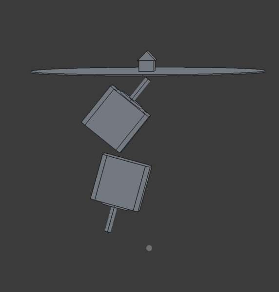
Motors like this?
The top one is parallel to the earth's axis, the bottom one is inclined by 23.44°. The top one spins once per day, the bottom one spins once per year. They're both arranged so that their axis approximately passes through the house, so that everything rotates around the house.
The upper motor will need to move down so that there is room to mount the encoder beyond its shaft. I'm imagining that the shaft will be keyed directly to some bracket on the frame, with its shaft poking through, and then a magnet holder will slip onto its end, and the encoder will be positioned just past the end, and attached to the rotating frame.
I may want smaller motors, this is looking quite bulky already.
Is it even possible to make sure the sun always orbits around a fixed centre point when we have two axes like this? Intuitively seems like it should be. I think you just need the axes to intersect the centre point.
In fact you could do it with just one motor! And gear the motion of the sun off the rotation of the earth. That is obviously the way you're meant to do it. And then I could have a single time/date indicator somewhere on the device and some jog buttons to move forwards/backwards in time when it gets out of sync. So just one motor, no magnetic encoder, gearing, and buttons. I want the buttons somewhat inconvenient, so that kids don't mess with it, and so that it doesn't spoil the appearance. And then there needs to be a dial somewhere that shows the time of year and time of day. Maybe just 2 hands, one for time of year and one for time of day? Also need something to indicate the year actually.
I think the ratio needs to be 366.256:1, I could be off slightly. The extra 1 is because of the extra rotation because of turning all the way around the sun.
I'm messing about with https://incoherency.co.uk/clock-gear-train-calculator/ to try and find a good set of ratios.
You can have 58:6 44:6 31:6 which is a ratio of 366.259259259... which is a negligible error, but needs 6-tooth pinions.
Alternatively 79:10 76:10 61:10 is 366.244:1 which is an error of about 1 day in 100 years, which I can probably live with. So then would I rather use 79-tooth gears, or add an extra stage of reduction?
So we're imagining that the motor would directly drive the earth rotation axis, and the sun rotation axis, 23.44° inclined, would have like a slight bevel gear running around a ring gear, which would slowly advance it? Or alternatively we could have a stationary gear up the middle of the rotating assembly? A large ring gear may be helpful as it gives us a lot of teeth to play with to sort the ratio out, albeit that the first gear on the rotating assembly will be going faster than the earth rotation rather than slower.
< 2025-11-15 2025-11-18 >