Last modified: 2025-06-08 22:08:32
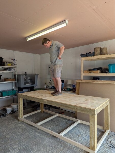
< 2025-06-07 2025-06-09 >Plywood top is now fitted, legs cut down by 50mm as it was a bit tall, diagonal braces underneath the plywood, horizontal braces on the lower level, and plywood lower level now fitted.
Next up is MDF on top, then mounting vices, and I think I'm done with it. Also want to do some sanding of the frame to smooth it down a bit.
(Plywood lower not pictured).
I'm thinking of writing a blog post on the list of reasons we tell children not to do things.
More generally:
So these are of 2 kinds:
And if you assume that others might exact some sort of retribution if you do something bad to them, it all comes down to:
Although hurting others is still bad even if you are completely sure they won't retaliate.
At the moment the sundial is exposed in the morning by the shadow of the ridge of the house moving back towards the house. I expect that at some time of year, it will instead be exposed by the low sun moving around the side of the house.
I took some measurements with the sextant, with the mirror approximately at the centre of the sundial, and the height read off the sextant and bearing read off the sundial as a solar time.
As viewed from the sundial, the silhouette of the house is approximately like this:
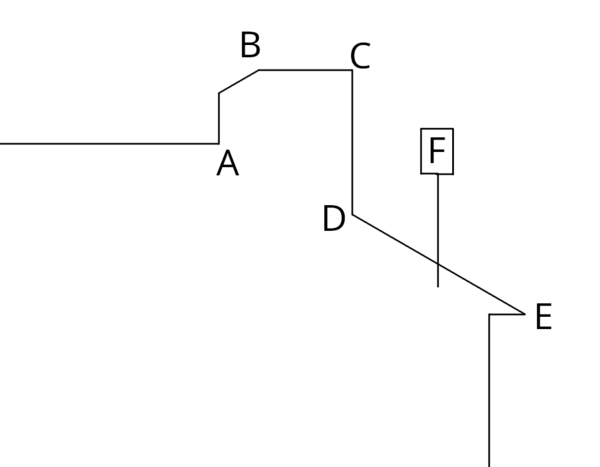
What dates will the sun be at those angles at those times? And then we know that the day before the shadow will be revealed up/down, and the day after it will be revealed left/right, and hopefully on the exact day the corner of the shadow will cross the surface of the sundial.
Obviously they are local solar time, so I want to convert to GMT and potentially BST to work out the actual time of day.
How do you work out the direction to the sun at a particular time?
https://www.sunearthtools.com/dp/tools/pos_sun.php?lang=en I think this tool does what I want.
Hmm, actually, I have misunderstood something here. The angle of the gnomon shadow is not the same as the angle of a vertical rod's shadow! So the time doesn't directly point to the sun direction. And actually I think the times I wrote down are the angles of the pm times.
So let's just convert those to azimuth angles.
And then dates and times (from trial and error on SunEarthTools) are approximately:
So I'm thinking of making Lucy a ride-on electric tractor, in the style of a https://en.wikipedia.org/wiki/Ferguson_TE20
So inspiration pics are:
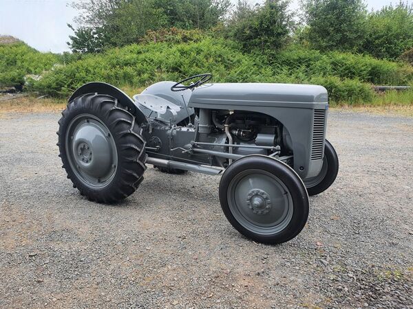
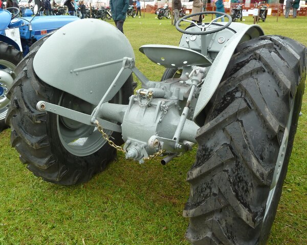
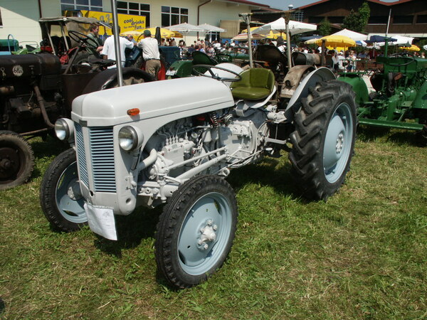
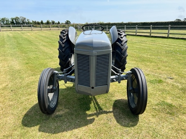
It doesn't really need to be a replica, just vaguely evoke the idea.
I'm thinking I'll buy an "electric go-kart kit" off the internet, that gets you a 350W motor, speed controller, throttle pedal, chain, sprockets. And then an ebike battery to go with it. And then the only other tricky part is wheels, you want the wheels to look about the right proportion for a tractor.
So my plan is to work out what sort of scale it will be, find some roughly appropriate wheels, and then mock it up in FreeCAD to see if it will look anything like a tractor.
I don't really know how/if I'm going to do the rounded bodywork.
Other inspiration is that "Toylander" do a kid's tractor as a kit: https://www.toylander.com/vehicles/tractor-mfr
It looks like this:
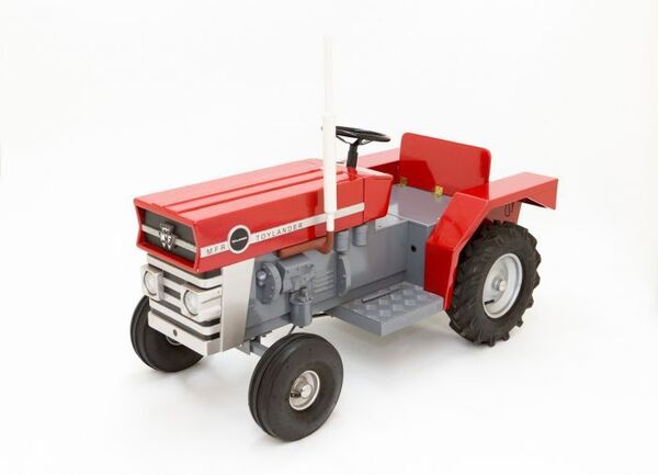
So there we see the main structure of it is basically a box that you sit on top of, and there are some foot plates at the bottom. I'm not going to do fake engine components.
On eBay I have found some wheels that are "18x6.50-8", which means the tyre is 18 inches outer diameter (457mm), 6.5 inches wide (165mm) and mounted on an 8 inch rim, they look maybe suitable for rear wheels.
From the reference pictures, it looks like the front wheels want to be a bit over half the size of the rears, so we'd want maybe 10 inch outer diameter.
It looks 10 inch tyres are very common for wheel barrows, sack trucks, etc.
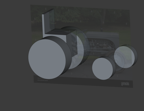
Mocking that up in FreeCAD, does it look like a child-sized tractor?
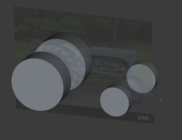
Maybe?
Hard to see without a child for scale.
That has a 500mm track (between centres of rear wheels) and 675mm wheelbase (between centres of axles).
Laying that out on the floor with a tape measure, I actually think it is too small.
I measured a chair that she sits on and put this in CAD:
Yeah it seems like the tractor is comedically small even for Lucy as she is now, so not very futureproof. Needs to be bigger than this.
If we look to go about 50% larger, we'd want 27 inch rear wheels and 15 inch front wheels. One issue is that tractor wheels are very large diameter and narrow compared to most of the wheels I can find, which means I'll probably have to compromise, which it looks like Toylander have also done, their wheels are too short and too wide.
"22x11.0-8" is available, but that gets us 44% of the way to the ideal diameter, at the cost of 70% extra width. Maybe I just go with the wheels I already found but scale up the track and wheelbase.
I think this looks a bit more reasonable:
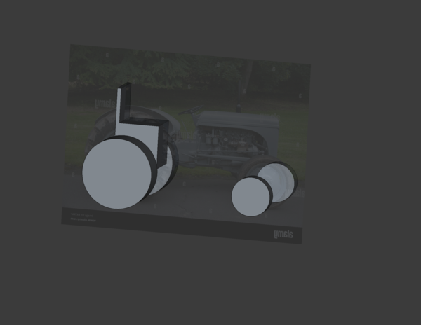
That's with 900mm wheelbase. I think that will be fine. Now maybe mock up the shape of the "box" of the frame? And check that the motor, chain, sprockets will fit inside.
Looks reasonable I think?
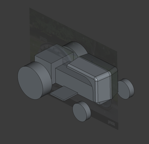
No idea how I'm going to make the bonnet. The motor etc. fits inside easily, so I've ordered the motor kit, a pair of second-hand 18x6.50-8 wheels that have some annoying-looking keyway fitment, and a pair of brand new 10 inch sack truck wheels with integrated bearings.
To fit this scale the steering wheel wants to be about 180mm diameter. So potentially 3d-printable.
< 2025-06-07 2025-06-09 >