Last modified: 2025-04-28 19:52:19
< 2025-04-26 2025-04-30 >The plan is to expose a plot of "torque" to the scope, showing torque applied to the pendulum from the escapement, and then see about adding an angle/torque plot similar to the pressure/volume plot on the oscillating engine simulator.
And then simulate a "Tekippe regulator" and reply to John.
I actually don't know how to work out the torque on the anchor. I can world.setAutoClearForces(false) and then look at anchor.m_torque - but it is always 0. I think because the torque
is applied to the anchor by a force instead of a torque.
Could I work out the implied torque on the anchor by looking at its angular velocity? And then subtract out what I know the torque from gravity would be?
Yes, that works.
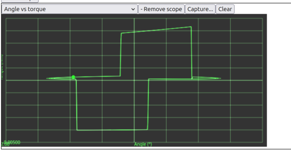
And I am getting somewhere with the plot, although there are a lot of glitches in the computed torque, I guess because of numerical issues in Planck.js.
Here's a glitch-free screenshot:
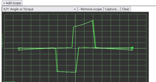
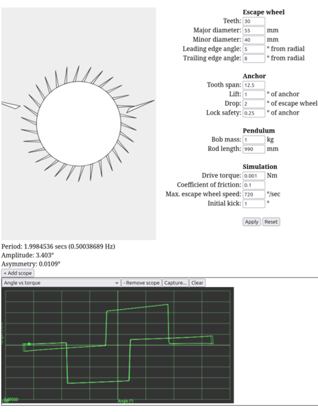
And the example from https://groups.io/g/Horological-Science-Newsletter/topic/clock_b_vs_tekippe_s_clock/112278009 is:
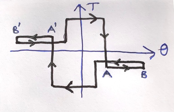
And here's another example:
That one shows:
One issue is that to get graphs that look this good I have multipled the computed torque from gravity by 0.0012738. I could maybe accept multiplying by 0.001 if there is a factor of 1000 confusion somewhere, but where does 1.2738 come from?
I think the "extra step" comes from the amplitude getting so high that the tooth actually falls past the "top" of the resting face, so is totally bogus.
Changing the rod length means I need to change my 0.0012738 factor, quite dramatically.
A rod that is 1/10 of the length wants the factor to be about 0.111, so about 100x larger.
Could it be that my pallets are actually really heavy? And approximating gravity on the pendulum by only looking at the bob is actually not right?
No, I have density 0 on the pallets.
OK, the issue may be that the moment of inertia of the anchor does not seem to depend on the rod length? Is that right?
Yes, I think that was it. I've made it calculate the pendulum moment of inertia itself instead
of using anchor.m_I and now I don't need the random fudge factor.
OK, good, so now how do I make it imitate a Tekippe regulator?
This is the clearest picture from the forum thread:
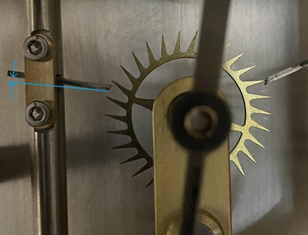
We see that the escape wheel appears to be very small. John said over email that the amplitude is only about 1 degree. And from the picture:
Initial attempt:
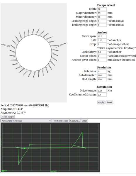
The angle/torque plot doesn't look very convincing.
This is looking a lot better:
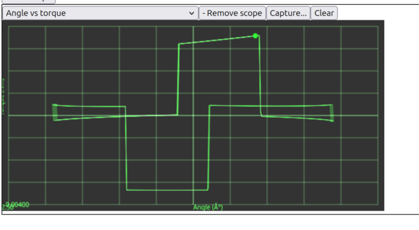
One thing I'm confused about is that the "loops" are the wrong side of the x axis?
A positive torque is pushing the anchor towards positive angles.
The largest-magnitude segments of the plot are the impulses.
If you ignore the vertical segments (step changes in applied torque) we have 6 horizontal(-ish) segments in a full cycle, consisting of 3 segments per half-cycle, or 3 segments per pallet.
Starting from the drop, you have (1) frictional rest as the pallet swings towards the escape wheel, then (2) frictional rest as the pallet swings away from the escape wheel, then (3) impulse, followed by a drop on to the other pallet and the cycle repeats.
What's interesting is that frictional rests (1) and (2) don't exert the same amount of torque at the same pendulum angle, even though the torque on the escape wheel is constant. Why is that?
Intuitively it is harder to push something "against" a sharp tooth than "with" it. Is that the answer? If so, I'm surprised the simulation reproduces that.
And the other confusing thing is that in my plot it looks like after the "right-going" impulse (right-going as we look at the plot), the frictional rest is actually acting like more impulse rather than like a brake? I'm guessing this is an issue with how I am calculating the resultant torque. It should be a negative torque when the angle is increasing and a positive torque when the angle is decreasing.
I could try reducing the time step and see if that error gets reduced. Not obvious that it helps.
I think there is an error in the paper diagram from above, I think the frictional rest should mirror across the x axis when the direction reverses. That way it is always retarding the motion of the pendulum rather than accelerating it.
I think my calculation of gravity torque is not quite right, and that's the reason for the rest torque being the wrong side of the x axis.
Changing the diameter of the bob changes the plot I get, which is not at all what I want. I want to model the bob as a point mass. But making the bob diameter very small leads to glitch spikes in the plot?
So instead let's calculate the pendulum moment of inertia taking the bob diameter into account, when we subtract out the gravity torque.
And that works, we now see negative resting torque when the angle is increasing and positive when it is decreasing.
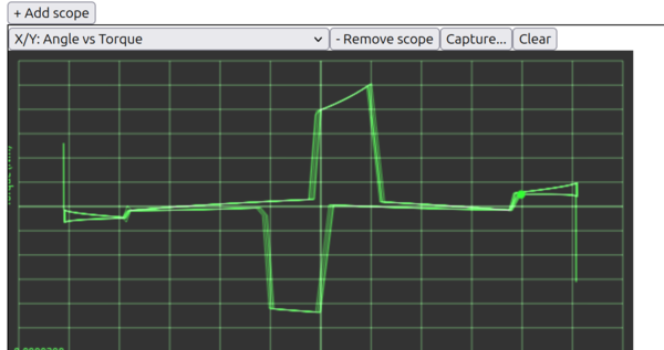
Now it looks like this:
So, better, but still asymmetrical. Why is the frictional rest torque in one direction so much higher than the other?
I tried setting the coefficient of friction to 0.0 and we still see positive torque from frictional rest: