Last modified: 2025-03-06 09:37:17
< 2025-03-04 2025-03-06 >So the plan today is to add a "document tree" to this, and then add ways to insert primitives, modifiers, and combinators into the tree, and render the tree into GLSL for drawing on the screen.
Primitives:
Modifiers:
Combinators:
And see Inigo Quilez's website for more, and for shader implementations.
I'm actually having more difficulty than expected in turning my tree representation into GLSL code.
The first attempt was to have the generateShaderCode() function return a single
expression, and have shaderImplementation() return code for supporting functions that
only wants to appear once.
So for example the Sphere generateShaderCode() would be sdSphere(p, ${radius}).
And a combinator would result in code like opUnion(sdSphere(p, 1.0), sdSphere(p, 2.0))
or whatever.
But then the problem is that we can't modify p. So we're propagating function
call code up the tree, do we need to be propagating p modifications down the tree?
But will that result in re-evaluating the modifications over and over again?
Or do we use shaderImplementation() to provide helper functions for every modifier?
Maybe that's the way! Just need to give them unique names. That seems to be working!
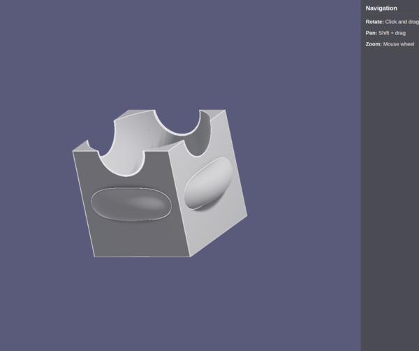
Now with:
Next up:
Somehow it keeps crashing Firefox. I keep getting back to the computer to find Firefox has closed.
One issue is it recomputes the shader every frame even if nothing has changed. Worry about that later.
I'm giving the tree nodes a function properties() that returns a map of property name
to type (currently just "vec3" and "float"). And then getProperty() and setProperty()
should be used to get/set, default to just writing into the object, but can be
overridden by each node.
So then we want a tree view, a property editor, and some way to add/remove nodes in the tree. And that's a CAD MVP.
Whoa, Cursor's first attempt basically works straight away, modulo UI jank.
It functions, it just needs to be more user-friendly.
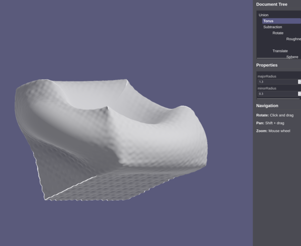
Now with editable "displayName", icons for different operations, lines connecting up the tree, resizable panel.
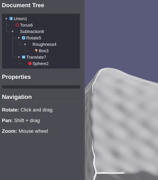
Can now delete a node, with a context menu.
Can add primitives with the context menu.
Can add modifiers/combinators with the context menu.
Can unlink a node so that its children become direct children of its parent.
Can disable edge detection in shader, and the edge highlight size is now fixed in screen space instead of object space.
Can disable individual nodes.
Still todo:
So one way to do this would be to make the sketch be a collection of "line segments", except we'd have the line segments be directional. So instead of the standard line segment SDF:
float sdSegment( in vec2 p, in vec2 a, in vec2 b )
{
    vec2 pa = p-a, ba = b-a;
    float h = clamp( dot(pa,ba)/dot(ba,ba), 0.0, 1.0 );
    return length( pa - ba*h );
}
(from https://iquilezles.org/articles/distfunctions2d/ )
We'd somehow modify it so that it gives you positive values on one side of the line and negative values on the other. Yes it would have a discontinuity at the ends.
So the SDF of a line segment is a middle region where you give the perpendicular distance to the line, and the end regions where you give the distance to the end point. I think we leave the end point distances alone, and just make the perpendicular distance go negative on one side of the line.
Then we can connect a bunch of line segments together and union them, and we have a continuous shape with a finite interior.
We could imagine doing something similar for arc segments, and then you can basically make any sketch that FreeCAD could do, short of Bezier curves. And ellipses.
OK, Inigo Quilez actually goes even further and gives a SDF for a polygon, maybe that is better than a union of lots of line segments. We still have the option of a union of line segments though.
Making a sketcher with constraint solver may actually be more work than the rest of the program put together.
You can attach sketches to faces by clicking in the window, raycasting from the click point to find the surface, then computing the normal from there and putting the sketch on the plane perpendicular to the normal.
It won't move when the other geometry changes though. Same problem with the idea of applying fillets by selecting edges.
< 2025-03-04 2025-03-06 >