Last modified: 2025-03-04 22:41:06
< 2025-03-03 2025-03-05 >I've been lying awake toying with the idea of making a SDF-based CAD program.
There are only 2 things I want to do with a CAD model:
If we say that an object in our CAD is represented by an anonymous function
of (x,y,z) that returns the distance from that point to the nearest point of our
object (negative if inside the object), then we have:
sphere(r) = func(x,y,z) x^2+y^2+z^2 - r^2
union(f1, f2) = func(x,y,z) min(f1(x,y,z), f2(x,y,z))
intersection(f1, f2) = func(x,y,z) max(f1(x,y,z), f2(x,y,z))
cut(f1, f2) = func(x,y,z) f1(x,y,z) - f2(x,y,z)
halfspace(z) = func(x,y,z) z
cube(w,h,l) = func(x,y,z) max(x-w, y-h, z-l, w-x, h-y, l-z)
translate(f,dx,dy,dz) = func(x,y,z) f(x-dx,y-dy,z-dz)
And so on. You can also imagine a "sketch" feature that lets you define a SDF
of only 2 dimensions with some Sketcher-like interface, which is then effectively
an infinite extrusion of your shape (considering that you disregard z), and to
pad it you intersect it with a slice of z covering the range you want, and union
with the existing part.
Benefits over traditional CAD are that it has much fewer edge cases so more likely to get it correct in less time, makes some cool operations easy that traditional CAD doesn't, and makes complex intersections etc. really fast to calculate.
The main downsides are that rendering is potentially complicated, not sure, I need to find this out, and any workflow that involves selecting vertices and edges is really hard to do.
So for a toy prototype you need a basic UI for specifying these objects, a way to render them on screen, and a way to 3d print them.
I'm not fussed whether 3d printing works by exporting a triangle mesh or by slicing directly from SDF. But it seems like if you can slice directly from SDF then you can make a triangle mesh almost as easily, and then you get the benefits of a "real" slicer.
Also slicing to triangle mesh would solve the rendering-on-screen problem at the same time, so maybe that's the way to go.
For rendering, ChatGPT suggests:
You can do ray marching in a shader, but the one downside there is that we've basically made "recompute" really fast by just making each operation a tiny function, but now our real recompute is every single frame as we have to evaluate the function.
You could imagine some scheme where we do a few passes of ray marching on progressively higher-resolution grids until we reach full screen resolution, and if the user is still moving the object around and a frame is due we just draw the highest resolution image we have. That way in steady state it will improve over time until it is rendered at full resolution, but you can still move around fluidly, as long as you accept a worse-quality image while you're doing it.
Not sure if anyone has done a CAD-like user interface for SDF modelling yet.
Interesting prior art:
Other resources:
One thing that makes it more tricky than I imagined is if your distances are
wrong then some operations won't work properly. For example if you scale something
by doing scale(f, k) = func(x,y,z) f(x/k, y/k, z/k) then the distances are not scaled
as well, so then if you do some operation that actually cares about the distance (like
a "thickness" for example) then the thickness will be wrong.
For a uniform scale I think you could do scale(f,k) = func(x,y,z) k * f(x/k, y/k, z/k).
but for non-uniform scale I'm not sure how you'd do it.
For applying fillets I wonder if you could "detect" edges for the user to click on by looking for places that have sharp changes in the normal direction, and then apply some modification to the SDF that is bounded to a region near the edge? The "sharpness" threshold could be configurable.
So you can tell that a point is sharp if it has normal direction very different to any nearby points. And you can tell that a point is part of a line if there is a nearby point that also has high sharpness.
So maybe you'd work out what point the mouse is hovering over, work out if there is sharpness nearby, and then spread out to find the edge(s), and then highlight the detected edge(s) as the place that the fillet will be applied?
The Wikipedia page on "Function representation" takes a simpler form, where the actual distance value is not required to be accurate. That means we have more freedom to do operations that distort the function, but no longer can use the distance for productive purposes. Maybe in practice it is just the same thing, because I can't see how you can do much of any use with the function representation otherwise.
This guy https://fornjot.app/blog/why-fornjot-is-using-boundary-representation/ says he looked at using F-rep but found it not viable because of the issue of useful operations that both depend on, but don't produce, correct SDFs.
So that is the key issue in F-reps for CAD. Solutions include:
Probably defer the decision for now, get some sort of testing environment setup and go from there. Maybe try out libfive Studio, although the OpenSCAD-style interface is definitely not what I want. I want something more like "Part Design" in FreeCAD.
Meh, I can't get libfive Studio to work.
$ studio/Studio
;;; WARNING: loading compiled file libfive/bind/guile/libfive/kernel.go failed:
;;; In procedure load-thunk-from-memory: incompatible bytecode kind
guile: uncaught throw to misc-error: (#f ~A ~S (no code for module (libfive kernel)) #f)
Segmentation fault (core dumped)
Even after I delete the Guile cache and recompile it, same thing.
How much work would it be to get an SDF playground working in the browser?
Wow, actually very easy, Cursor is really good at this.
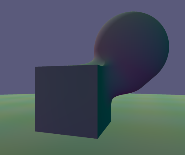
That is from 3 prompts: 1 to setup a WebGL canvas, 1 to draw a SDF, and 1 to specify that I want 3D SDF instead of 2D.
With a bit more work, and still almost entirely prompt-driven-development, we have:
So now for each of the objects I can make it subtractive and/or make it a "shell" with some thickness instead of a solid.
I think next step would be to change it from just ticking the hardcoded shapes on/off into some sort of editable "scene graph" where I get to add new objects, and edit their properties, and combine them together with other operations, etc.
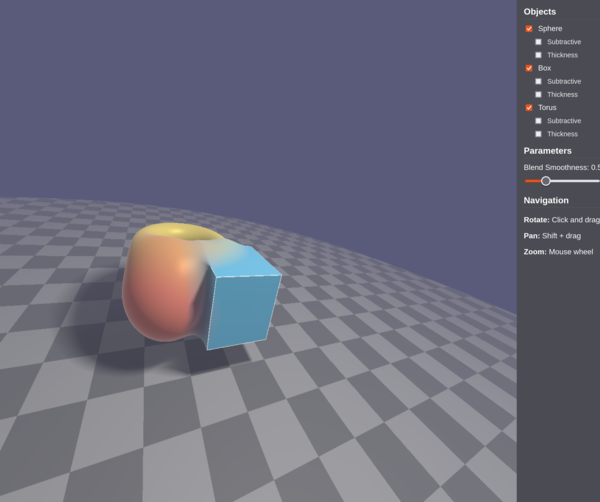
I had it refactor everything and it also made the graphcis way cooler:
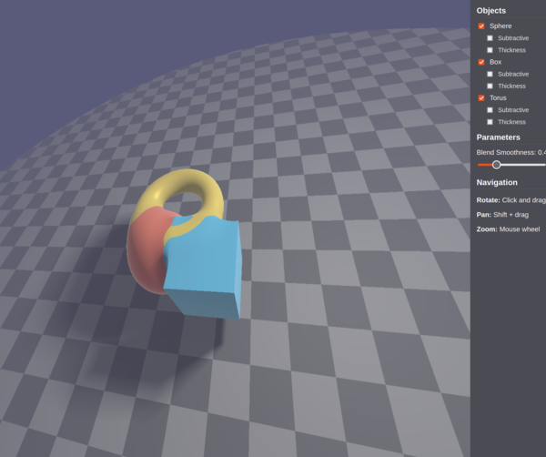
But yeah, next step is thinking kind of deeply about the scene representation, and move towards "actually designing the program" instead of just random AI code.
I think with a day's work this ought to be able to actually work as a CAD program.
Let's start with the "Part" workflow.
We want:
And that's your MVP done.
I think basically everything that can go in the scenegraph needs to have a GLSL implementation for use in the viewer, and a JavaScript implementation for use in making a triangle mesh.
And then for more complicated objects we will need a way to render at lower resolution while redrawing or whatever, so that we still get frames at a decent rate?
And then phase two is to make a "Part Design" workflow, so we'd have a "Sketcher" mode that lets you create a 2D SDF out of some sensible 2D primitives. (To get a 2D SDF demo page, checkout "Initial commit" of sdf project, and get Cursor to change it to draw an SDF, it defaulted to 2D the first time I did this, and worked, but I wanted 3D so I didn't keep it).
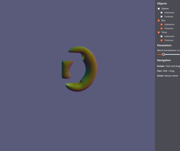
Last thing for now: I made it highlight sharp edges with the method I described earlier (look for discontinuous normals) and it looks like it works:
Although not obvious what is meant to happen where the edge just smoothly blends in to a non-edge, in the case of filleting for example. Maybe SDF magic makes it all work out on its own.
https://iquilezles.org/articles/distance/ this page seems to present a general formula for turning a non-SDF F-rep into an approximate SDF. Just divide the value of the function by the length of the normal?
I think to start with we can take several types of node in the scene graph:
Primitives take no nodes as input. Modifiers take one node as input. Combinators take multiple nodes as input.
We should probably eventually make translation, rotation, and renormalisation into properties of each node rather than (or as well as) individual nodes in their own right, since they'll probably be used quite often.
And then just like in FreeCAD we'll have some properties that are common to all things, and some properties that depend on the type of thing.
The root of the scene graph should be an implicit union, so you can just add and remove extra objects to the scene.
Each input to a modifier should have a checkbox or something that allows disabling it.
Also we should have a way to stop viewing the root of the scene and instead view some subtree, or multiple subtrees.
What should the scene graph UI look like? Do you really want dozens of nested layers of indentation tree?
And, should the scene graph be a strict tree or should we allow it to be a DAG? Can an input to one modifier/combinator also be reused as an input to another?
Allow drag-and-drop to move things in the tree.
Support robust undo.
< 2025-03-03 2025-03-05 >