Last modified: 2025-03-07 12:44:08
< 2025-03-05 2025-03-07 >Instead of working through the todo list, I think a good benchmark would be how efficiently I can recreate some CAD practice parts, in Isoform compared to FreeCAD.
I'm going to have a go at the first one.
I think it can be made out of cylinders and boxes, although that is obviously not the most natural workflow in the world.
While I'm working I'll notice things that can be improved and improve them.
Actually before I start I am going to work on making it work in millimetre scale, so the units are millimetres.
I think zoom wants to work by moving the camera in/out instead of by scaling.
OK, I've messed around with zooming and lighting and stuff for long enough now, it is improved though:
So now, time to try to model the example part.
Starting from a blank document at 10:45.
The last part seems to lock up the entire program, so that definitely needs fixing.
Oh! It's because they're not actually stringwise identical, because they call different functions, so it generates each copy separately even though it is uniq'ing them. Meh, I guess each modifier node needs its own function then. At least we get to lose the "signature" stuff.
Great, fixed.
10:59, let's have another go at modelling this part.
11:12 I have this!
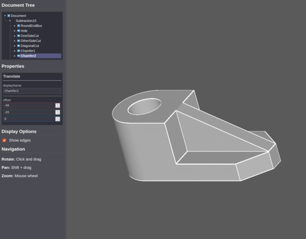
OK it took 13 minutes and in FreeCAD would only take a couple, but I only have like 1 day's work in this entire CAD program.
Just noticed it is not quite right because the chamfers are meant to be 9mm wide but I made them join up with the web. Never mind. One thing that is really difficult is accurately positioning things. That's where the Sketcher workbench works really well. So one big advantage of B-rep is it gives you concrete edges to reference.
And I can fillet it by setting radiuses on things, and on the subtraction.
But again it would be better if you could explicitly choose which edges to fillet. For example you might want the outside filleted but the inside of the hole with a sharp corner.
Let's look at adding rotation/translation as a "generic" property of all nodes.
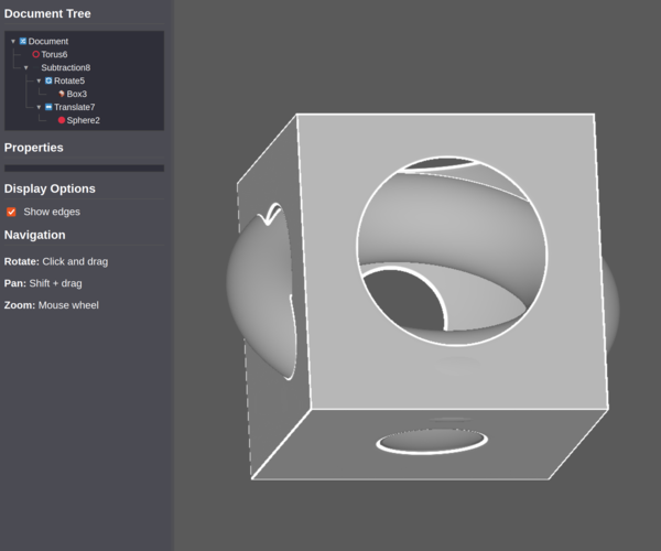
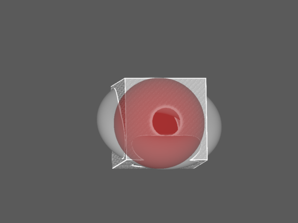
Here's an example where roughness is applied only to the "hole" feature:
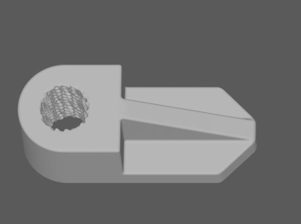
Absolutely incredible, this is the stuff dreams are made of. And I literally have no way to make something like this in FreeCAD. The best I would be able to do is write a program to break up a triangle mesh into tiny triangles and then permute the coordinates of the triangles. But the SDF lets me target the permuting to particular features of the tree. So good.
So the tree re-expands all collapsed nodes whenever it gets rebuilt, and it gets rebuilt quite often. One option is to remember the collapsed state and restore it upon rebuild, another option is to reduce the number of places we need a full rebuild, and edit it in-place instead? Probably safer to do full rebuilds all the time and just make them work properly.
Done.
And the next really important thing is showing the object you're currently working on, so you can see where it is. I like the idea of doing a second rendering pass, with just that object enabled, drawing the background transparent, the object in a different colour, and maybe reduced opacity.
But I don't like the idea of having to reset the shader twice per frame. Do I load a second fragment shader? Do I compile a fragment shader that does 2 rendering passes on its own? Probably that. So we'd have basically 2 "map" functions, and correspondingly 2 lots of ray marching, normal calculating, etc. And maybe a parameter for turning off the secondary render when we don't want it?
Sweet, done:
When one of the inputs in the property editor is focused it shows that node in red.
One issue is that if the node has rotates/translates above it, we don't apply those. So I think when we draw the selected node, combinators turn into no-op but modifiers still apply? There are actually 2 types of modifier: coordinate transforms (which should still apply) and "surface treatments" like roughening etc. (which should not).
Maybe we give each node type a flag saying whether it should be applied when doing secondary render. Great, works.
Now allowing arithmetic input in property editor.
I think I want a X/Y/Z axis direction representation in the corner. And then we can do view planes.
Wow this is actually super duper hard. It should be easy! I'm just not good enough at
the maths, and Cursor isn't either. I am confused why this isn't trivial. One issue
is that rotatePoint rotates the point before evaluating the SDF, which means we
kind of need the opposite rotation now?
Ridiculously, I've made it work by defining an SDF for the axes and raymarching it...
Also, lol, just worked out I have a left-handed coordinate system. Need to fix that.
Also I need to be able to rotate better, currently the X axis is always horizontal on the screen. And then next up is jumping to orthogonal view planes.
So remaining things that would immediately speed up the demo part:
And other todo:
Secondary mode doesn't work properly on a transform(roughness(box)). It seems like
when you evaluate the transform, it then evaluates its child nodes in full, without
checking whether they should be suppressed because of secondary mode.
Ah! It's because the transform calls its child by a call to
shaderCode() inside shaderImplementation()! So it doesn't know to suppress it.
Drat. Do we make shaderImplementation() also be aware of secondary mode? Probably.
Well that felt kind of hacky and like I made some mistakes, but it looks to be working. It is an improvement over what was there before at any rate.
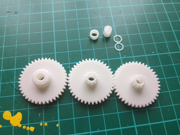
My 0.2mm nozzle has arrived, so I'm going to print out the gears and shaft spacers now. Will then switch back to the 0.4mm (or maybe even 0.6mm? haven't used that one yet) for the wheels, chassis, and flywheel.
Changing the nozzle turns out to be quite a faff. Next time I would get the version that comes with the thermistor, heater, and fan already attached.
These look great:
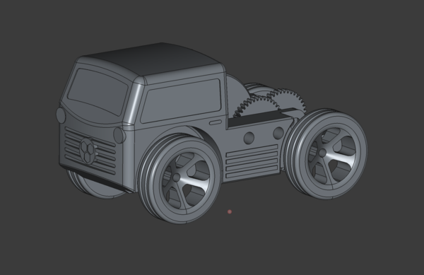
And some work on a body:
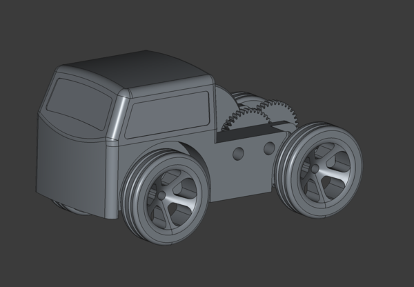
OK, here we go, stopping now:
Slicing this on "standard" settings:
So actually the 0.6mm nozzle doesn't really get you very much, and the quality will be worse due to the increased layer height, and I don't want to have to bother changing the hotend again.
So I've just put the 0.4mm nozzle back on now, need to print the chassis, flywheel, and wheels, then cut shafts to length from 5mm aluminium rod, and cross-drill the rear axle for pinning to the axle gear, then assemble and test it out!
< 2025-03-05 2025-03-07 >