Last modified: 2025-03-02 22:17:07
< 2025-03-01 2025-03-03 >I have put the clock together, with the extended bearings and also with fishing line instead of polyester string.
The fishing line is most inconvenient because it all tangles up if it's not under tension, but it does seem to be less stretchy than the polyester.
The clock still doesn't quite have enough power to wind the remontoire.
I took the weight tube out and brim-filled it with lead shot. Forgot to weigh it but my guess is about 1/6 heavier, so maybe 3.5kg now.
Didn't make much difference.
The next idea is to cut the "remontoire weight" down so that less torque is required to wind it.
This might have done it! It has successfully wound, straight away, twice in a row.
It doesn't seem "powerful" though. But maybe will do for now, I'll leave it and see what happens. It is 17.03.
It stopped within 10 mins with remontoire completely unwound :(.
Though that may have been down to the very scruffy wind of the fishing line on the drum. I've rewound it neatly and set it going again at 20.04.
At 21.39 it looked like stopping. I tapped the frame with my finger and it wound the remontoire and kept going.
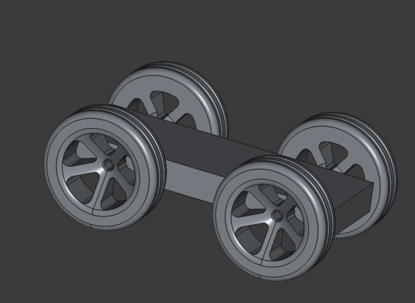
This is a platform and wheels of approximately the size I want:
The wheels will take o-rings in the grooves, I may need to resize them slightly to suit the available o-rings.
The wheels will go on 5mm axles with micro ball bearings pressed into the chassis.
So now the plan is to lay out an "optimistic" gear train and flywheel. Since I think there is some risk of getting the gearing wrong on the first try, I will probably make the bearings for the shafts go on a separate piece that screws down to the main platform. Then when I inevitably change some ratios, I can modify the bearing locations without having to reprint the entire chassis.
And then once the gear train and flywheel are laid out, and the shaft bearing piece is ready, I will come back to the "platform" and modify it to look a bit like a flat bed truck with a load of gears on the back.
The wheels are probably on the large side, but that is beneficial for climbing over obstacles.
Btw I have ordered a hotend with 0.2mm nozzle from Bambu, because I think I might want the precision for printing the gears.
I'm going with module 0.8 for the gears. The only gear that needs keying to a shaft is the one on the axle. For the others a press-fit is fine as long as the gear and pinion are a single piece. I could cross-pin the axle gear?
Update: I think forget the idea of making the bearing mounts a separate piece. Just make it as one and see if it works.
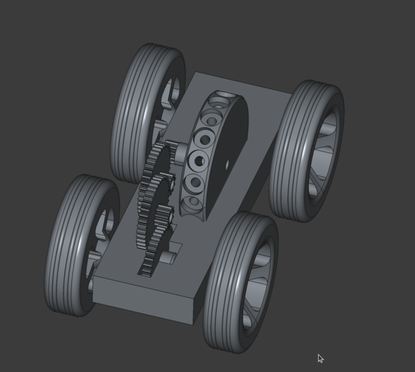
The overall gear ratio is 64:1, 3 stages of 4:1. ChatGPT says this is more extreme than most flywheel toy cars, I don't know if it actually knows though. Will just have to wait and see how well it works.
The flywheel is spinning "backwards", so if the flywheel catches on obstacles it will impede progress rather than helping to climb over it. Never mind.
All the shafts are intended to be the 5mm aluminium rods.
The flywheel will take 18x M5x10mm button-head allen screws as weights.
Next steps are: