Last modified: 2024-08-26 20:22:20
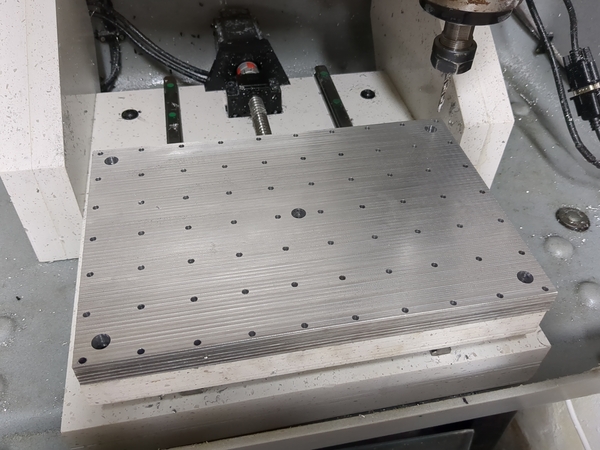
< 2024-08-25 2024-08-29 >Now that the table is surfaced I can sweep an indicator across to work out how perpendicular the spindle axis is to the table surface.
That won't tell me anything about how accurately the Z axis moves parallel to the spindle axis, but it's worth looking at anyway.
At a radius of about 19mm the depth only varies by about 0.01mm, and even then it varies by about that much depending on whether I'm touching the spindle. So actually I think the tram is very good. So why is the table surface not flatter?
Dragging the indicator across the surface in the Y axis shows the needle bouncing by about 0.01mm, so I think 0.01mm is just the roughness. But why is there so much roughness if the spindle is perpendicular to the table?
Maybe a 19mm radius isn't enough to show it? But it should be, if we've got 0.01mm roughness from a 1.5mm stepover?
Forget it for now. Move on to drilling holes.
I'm going to first try to drill them with a 4mm drill, then once that is done open them up with 5mm, then probably take the table off and tap them on the bench.
For a 32mm grid we have 288mm between the outer holes on the X axis (12mm short of full length, so first one is at X=6), and 192mm on the Y axis (8mm short of full length, so first one is at Y=4).
The "lathe speeds" chart suggests 2500 to 10000 rpm for drilling aluminium with a 4mm HSS drill. Let's start at 6000.
It's chip-welding badly with 100 mm/min feed. If we feed faster? 200 mm/min seemed a bit better. Try 300.
Still chip-welding. Looking online suggests reducing the speed to reduce the temperature. So let's try 4000 rpm and 200 mm/min.
Seems better, we're getting further. Just doesn't quite have enough torque. I'll try reducing the feed rate to 150 mm/min.
Now down to 94% feed (140 mm/min) and 95Hz (5700 rpm). I'm increasing the speed on the VFD because it keeps stalling.
Grid of 4mm holes:
Now open them up with 5mm. Starting out with the same settings as I finished the 4mm holes. I expect less trouble because there is less material to remove.
Ugh, it's bird's-nesting really badly. It's drilling nicely, just won't break the chip.
The answer is to feed a lot harder. I'm now at 4900 rpm and 256 mm/min and it is just about breaking.
I did probably half the holes at these settings. It looked like this at the end:
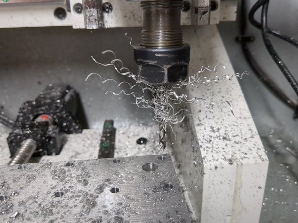
But it was roughly shedding bird's-nesting at the same rate as it was acquiring it. And it wasn't quite stalling at the bottoms of the holes. Anyway, done now, great success. Time for tapping.
Tapping is very time-consuming, and now the cordless drill battery is flat so I have to wait. Making progress though. I've done all 70 holes with the smallest tap, and about 24 with the medium-sized tap.
I did experiment with putting an elastic band around the anchor to act as a bit of a spring pulling it towards the centre position, but it wasn't very effective and the escapement still didn't work.
What if we literally just do it like a normal anniversary clock? Suspend the balance wheel from a piece of spring steel and twist it? Would it have to be a flat spring or would round wire do? I could try twisting a piece of the piano wire I have and see what happens.
It actually looks like it might work OK.
I clamped a length of piano wire to the ceiling and suspended a pair of mole grips from it, gave it a good swing, and filmed it oscillating for 5 minutes.
Here's the tick rate over 3 minutes:
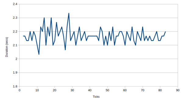
Pretty constant! Working out the end of one tick and the start of the next is quite subjective because the mole grips wobbled around a lot, but you can see that if you ignore the noise it is almost perfectly constant. There's no obvious trend either up or down despite the amplitude decreasing by probably a factor of 10 or more.
This may be the most isochronous mechanism I've ever plotted, which is hilarious/depressing considering how janky the setup was.
But it means I should definitely try to use this sort of thing for a clock. I should make a balance wheel that can be suspended by a single strand of piano wire, and make an escapement that can be operated by a fork mounted on the wire like a traditional anniversary clock.
I was wondering about how you would regulate an anniversary clock like this, because it doesn't seem like you can easily vary the attachment point of the spring. And if you want to move the weights on the balance wheel then you have to re-balance it every time you adjust it.
From this video: https://www.youtube.com/watch?v=ako9g_rkKB4 it looks like the weights on the balance wheel are on levers and you can wind a nut up/down to change the angle of all of the levers at once, pretty clever. Probably I want something simpler though.
I was wondering if you make one/both of the "banking pins" adjustable, would that change the rate of the clock? Seems like it might, but if you only adjust one of them then it will be asymmetrical which might negatively affect isochronism, and if you have to adjust both then you basically have the same problem as trying to adjust all the weights on the balance wheel at the same time.
What if there was a plate near the anchor pivot, and an arm sticking both "up" and "down" near the pivot. When it turns clockwise the "up" arm leans to the right and stops against the plate. When it turns anticlockwise the "down" arm leans to the right and stops against the plate. And then you can adjust the banking symmetrically just by moving the one plate.
It's not ideal because I think you'd rather not change how far the anchor is moving, and I don't know how much adjustment of the rate you'll get within a sensible range of motion of the anchor. But it might work.
< 2024-08-25 2024-08-29 >