Last modified: 2024-08-13 20:14:26
< 2024-08-11 2024-08-16 >I looked at changing the VFD to vector control mode, but apparently it's already in that mode.
So now I just want to check the configuration for the motor (1.5kW, ~7 amps, 220v?) and if that's OK then I think I can't get any more torque out of it at low speeds.
It was set to 6.4 amps, but that's probably about right, works out to 1.4kW.
I'm also not going to worry about cable management, I think this is all fine.
So next up is probably shimming the gantry. I want to repeat the measurement so that I know I'm definitely doing the right thing.
Going up by 84mm moved the indicator by 0.04mm. And after I moved the "cylindrical square", it then moved by about the same amount but in the opposite direction.
So actually I'm saying the gantry doesn't want shimming. The test cut from yesterday does have some slight steps in it, but on closer consideration it seems to be the difference between climb milling and conventional milling. Probably with a lighter cut that would disappear.
So next is putting some holes in the table to glue in some threaded inserts to bolt the aluminium surface down to.
I have M6 inserts 10mm diameter and 25mm long. 25mm long means they'll need to go all the way through the table.
And the mounting holes on the vice are about 96mm between centres, so I probably want provision for bolting the vice down directly as well. I will want to be able to bolt it to the aluminium surface too, but it would be handy to be able to bolt it directly to the table so that I get the extra 20mm of headroom.
It's a "VEVOR 80mm heavy-duty milling vice".
And I want the holes to bolt the vice down to be about 90mm from the back of the table.
Apart from that, there is a tradeoff in holding down the aluminium surface. I want it to be clamped down sufficiently, but I don't want to have excess screws because that creates table area where I can't support work or tap holes into the surface.
I think the corners are a safe bet for holding the aluminium plate down, because I usually want to attach clamps along the edges, rather than in the corners. I think one in each corner, plus one in the centre to keep the plate from being able to flex too much.
And then I want a grid of threaded holes in the plate that I can attach other things to. I think a 50mm grid so that it is nice and predictable, and 100mm spacing should still be fine for attaching the vice.
No, this is no good. I definitely want some bolt holes right at the edge, because then I can fit clamps around larger pieces of material.
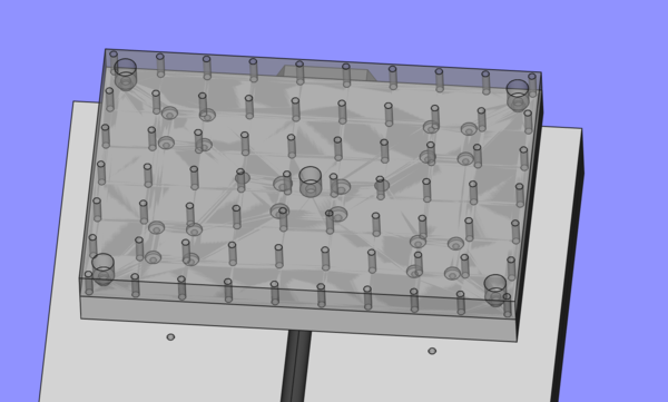
Here is a 32mm grid, with 10 across and 7 down. I think this will do, and gives us a nice 96mm for affixing the vice.
I wonder if this machine can drill the holes, or if I have to machine them.
< 2024-08-11 2024-08-16 >