Last modified: 2024-01-03 11:30:34
< 2024-01-01 2024-01-03 >Looking at the animation again:
I think if the end of the impulse face were hooked back a bit, then we would let the escape wheel move faster towards the middle of the impulse and slower at the end. That would have the effect of applying more of the impulse closer to the dead point. And it also has the benefit of slowing down the escape wheel before it lands in frictional rest.
The fact that my 3d-printed model needs a new balance wheel every time I want to change the shape of the roller is a clue: the roller table should be a separate component so that it can be modified more easily.
I'm going to print these parts:
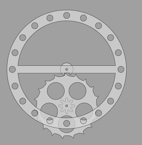
The shape is a bit different and it now fits 19 teeth on the escape wheel, mainly because the distance between the escape wheel and the balance shaft has increased.
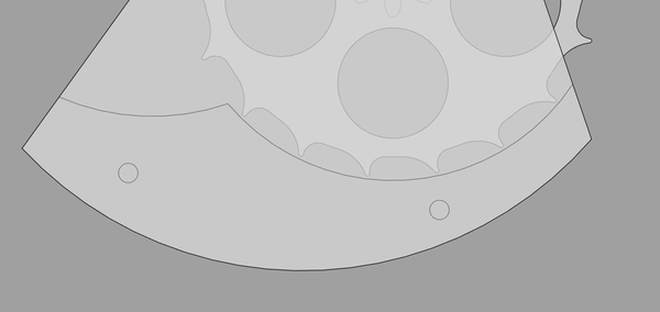
There's not a lot of clearance between the escape wheel and the balance cock, because the escape wheel has got bigger:
I'm going to print these parts now and consider what to do about the balance cock while they're printing. Worst case I can print a new balance cock.
Well it doesn't work very well.
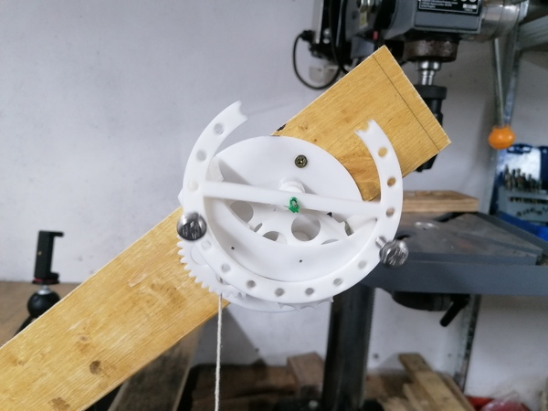
I realised that the balance cock is optional because the shaft it is running on sticks into the mainplate so far that it holds itself. Just needs a cable tie to stop the balance wheel falling off the shaft.
It doesn't work very well because it does not provide enough impulse to the balance wheel.
I now see that the duplex escapement is barely any more complicated than the roller escapement, it just requires aligning the two escape wheels and two rollers. However in my case I can probably make both rollers in one piece, and both escape wheels in one piece, because I'll be machining them with the CNC router, which means I get to do all the hard alignment work in CAD. I should probably use a duplex escapement, it is superior to the "roller escapement" because it gives a larger impulse. It is basically a roller escapement but with an extra (smaller) escape wheel, and an extra (larger) impulse surface.
This video has a good demonstration: https://www.youtube.com/watch?v=kULgoiQ8EXQ
The duplex escapement was difficult to make but achieved much higher accuracy than the cylinder escapement.
For my purposes I think the duplex escapement is easier to make.
And the video also appears to exhibit a machined balance spring, very interesting. I did consider the idea of machining my mainspring, but discarded it as obviously absurd, but maybe it is a good idea? With a 1mm end mill I can make 1mm gaps between the coils (in the relaxed state), and can in principle make the coils themselves arbitrarily thin. I'd machine the material to almost-final-thickness on the lathe, then use the router to cut the spring shape to its full depth, then fill the gaps with some sort of wax or glue that I can remove later, then use the lathe to cut the bottom off, exposing the completed spring.
So once I've found out whether this latest roller escapement model is better or worse, I should look at CAD'ing a duplex escapement where the wheels and the rollers can each be made as single 3-axis parts.
Update: it's worse, so... on to CAD'ing a duplex escapement.
In duplex-escapement/3dp-model.FCStd.
There's an article here with some pictures of a historical duplex escapement: https://www.thenakedwatchmaker.com/blog/2021/6/21/a-special-escapement
I'm just going to add a second level to the existing hook-tooth roller escapement model.
Actually I don't think that will work, because there are too many teeth, so not enough space for the impulse pallet to pass between the adjacent impulse teeth. I'll re-read Daniels' section on the duplex escapement and then think about what to do.
Important points:
A small drop occurs between the completion of the small impulse and the commencement of the main impulse. A second drop occurs on the completion of the main impulse.
&
To prevent the escapement setting, the small impulse must occur equally either side of the centre line with the quiescent point of the spring set at the centre line. This will ensuring escaping at amplitudes only slightly in excess of the escaping angle.
&
The escapement needs the lowest possible ratio between the locking-teeth diameter and the roller.
because a low ratio reduces the unlocking angle, however it also increases the friction.
Its construction requires most careful and skilled workmansip if it is to work well. The intersection of the roller and locking teeth is shallow and tripping will occur if the pivots are slack in the jewel holes. The pressures of the action of the escapement are high and all holes should be jewelled to prevent wear to the pivots.
Lol, that's all bad news!
I am having some trouble laying out a duplex escapement in CAD, need to carefully read Daniels again and study the diagrams. For now I'm going to go back to trying to make the thin mainspring barrel work.
To try to free up the shaft I'm going to put some autosol on the pivots and run it with the cordless drill. Hopefully this is not too aggressive.
I ditched the Autosol, just used 3-in-1 oil, and switched from the cordless drill to the lathe and then the process went a lot faster.
It spins freely now, but if I try to turn just the shaft, it still feels like there are potentially some tight spots. I think the hub is able to tilt slightly and then the largest diameter binds against the inner surfaces. I might want there to be a shoulder at the centre of the hub so that the axial alignment feature has a smaller diameter.
So next up is machining the slot for the hook at the inner end of the wire.
I may have an issue, in that my end mill only has flutes for 3mm and then tapers outwards, but the stub on the shaft is longer than 3mm:
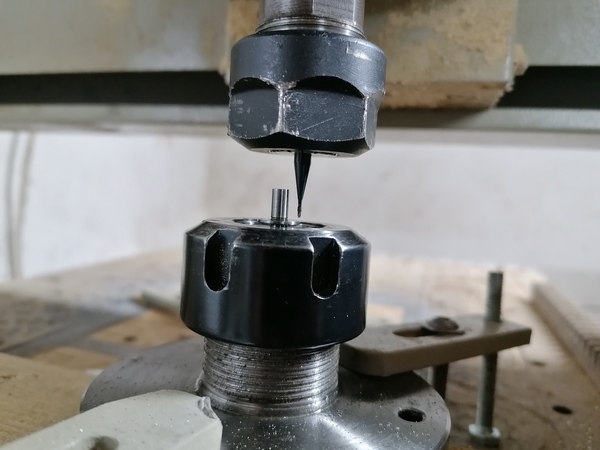
So the taper will interfere with the shaft. And part of the hook needs to be cut almost right up to the shaft, so there is almost no clearance there.
I'll probably turn a shoulder on the shaft to provide clearance for the taper.
Great success:
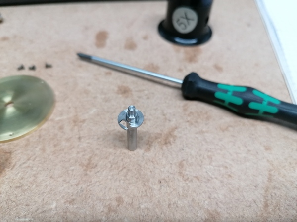
Another successful steel-machining job. The recipe is:
Successful machining aside I don't actually know if this will be a successful part. It looks very flimsy. At least it might mean I can close up the hook to capture the wire better.
And the hook fits nicely in the slot:
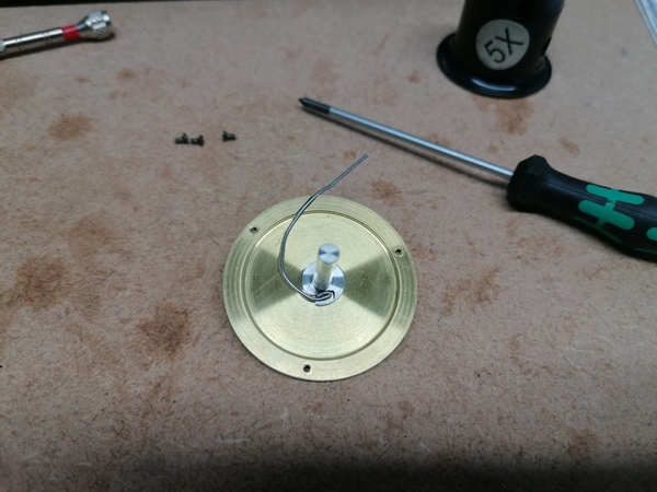
I screwed the barrel together and wound it using the pin vice, and it worked nicely, albeit quite hard to turn. The wire was already a bit crooked so I think it was binding slightly.
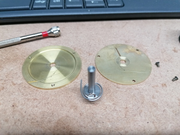
Pretty good! Although this wire doesn't appear to be exceptionally springy. Also it has scored the inside of both the top and bottom of the barrel.
But I'm happy with this for now. I've ran out of time for today but the next thing to do is wind a longer piece of wire onto it and see if it can provide any torque. Exciting.
It would be really handy if FreeCAD could show me 3 views of my parts, each with a separate rotation, but if I modify one of them then they all get modified.
Let's say for sake of argument that we want to match Breguet's duplex escapement geometry, as reported by Daniels:
How do I actually lay that out?
< 2024-01-01 2024-01-03 >