Last modified: 2024-05-01 19:31:36
< 2024-01-02 2024-01-04 >Found this on YouTube: https://www.youtube.com/watch?v=59rCIruI2cc
It has 2 locking teeth, close together, for every impulse tooth. The advantage (for me) being that the escape wheel turns more slowly and therefore less gearing is required of the train. The disadvantage is obviously that you waste more energy on frictional rest (but if you can lose a wheel in the train, maybe you get that back anyway?).
But let's try and lay out a normal duplex escapement first.
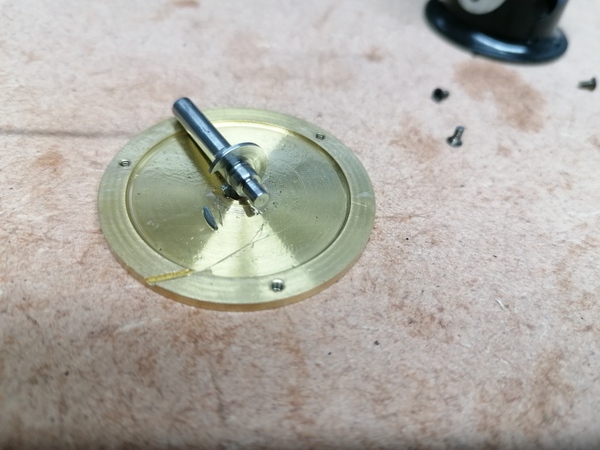
It took me several tries to assemble the thin barrel with the loop of the spring actually catching in the hook. Eventually I realised that I had cut the end of the wire in the wrong axis so the sharp point was driving the hook apart and letting the wire slip out. I re-cut the end of the wire perpendicular, so that the sharp point will catch on the hook, and this worked a bit better, but by this time the hook was too fatigued from being bent and it broke off:
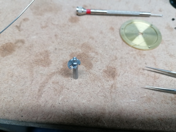
But also, the slot in the hub was much larger than it needed to be. I could do the same thing again but make the slot smaller (so that it is stronger) and I bet it would work.
For now I'm just going to try and cut a second slot in the existing hub.
Well I made this:
I snapped the old 1mm end mill while trying to probe the coordinate system, and replaced it with a fresh one, which I expected to work better, but it raised an awful burr.
I recall that the old end mill had 1 cutting edge broken, but maybe that was a blessing in disguise because it turns it into a single-flute cutter. So:
Being able to make my own cutters would be very handy, although it is faff. For stuff like this (i.e. no plunging) I think a D-bit might work OK. And that then opens the door to even smaller end mills. Definitely something to investigate.
I put it together, and the first impression is that it is winding! It is winding really nice and evenly, but does not appear to be remotely springy.
Here it is fully wound:
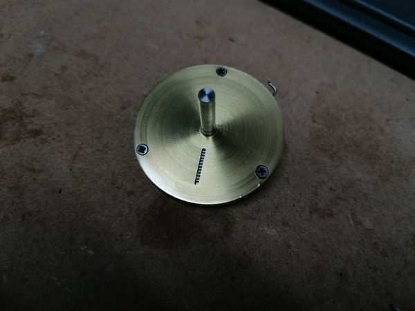
It is displaying no tendency at all to rotate the shaft on its own.
I loosened the screws slightly and it looks like it is... almost working? Sort of working? I only get about 3/4 of a turn on it before it starts to bind up, and if I keep trying to turn it after that point then it won't unwind on its own.
I think the wire is too long, i.e. has too many coils inside the barrel, so there's not enough room to wind it up/down.
https://www.youtube.com/watch?v=kk_LUHZPmsI
OK, I have some thoughts on how to layout the escapement.
If we want an unlocking angle of 60 degrees, then make the slot in the impulse roller symmetrical, and position it so that when the roller is rotated to -30 degrees, it is only just able to accept the locking tooth.
Since it is symmetrical, this means it will allow the locking tooth to escape at +30 degrees, which gives our 60 degrees unlocking angle.
Now to get 45 degrees impulse angle, we need to make sure that the impulse pallet is radial to the roller, and when the roller is at +32 degrees (escaping angle, plus drop to impulse) then the impulse pallet is at -22.5 degrees from the line of centres between the two wheels, and that at this position the impulse tooth is just touching it, while the locking tooth has just left the roller.
That means that when it moves around to +22.5 degrees, the impulse tooth will be just about to stop touching it, and then we've achieved our design unlocking, drop to impulse, and impulse angle.
Then we need to adjust the number of teeth on the escape wheel to achieve the desired drop to the next locking. And if this can't be achieved then something about the proportions needs to be changed, and try again.
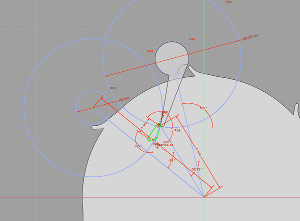
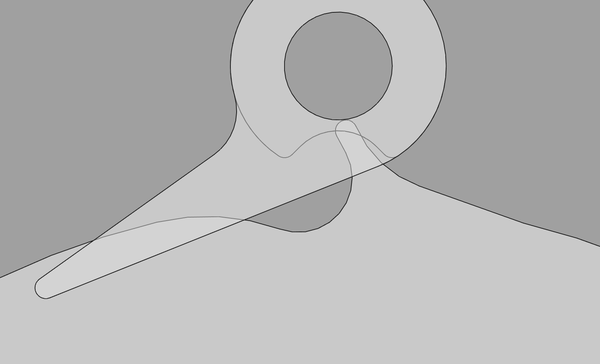
Well I tried the instructions above, and I got this sort of layout:
Which is obviously not going to work, because on the reverse swing the impulse pallet will interfere with the impulse tooth.
OK, maybe the circular impulse tooth is suboptimal, but changing the shape isn't going to solve the problem.
The diagram in "Watchmaking" page 206 definitely has the impulse pallet radial to the roller, so that's not the problem:
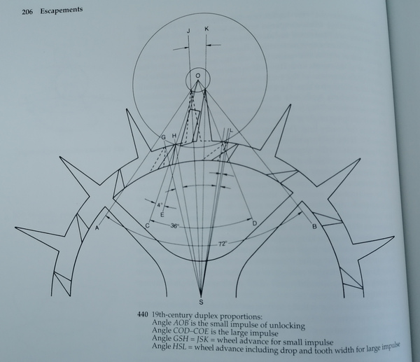
Maybe my issue is that my escape wheel is too small relative to the roller, so the rotation of the escape wheel for the unlocking is too large. You can see in the diagram that the escape wheel hardly moves during the unlocking. Almost all of the escape wheel rotation is during the impulse. Intuitively that is what you'd want, because any escape wheel motion not spent on impulse is wasted.
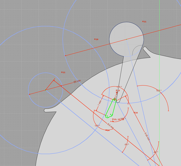
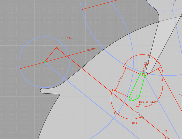
OK, here's a technique:
Plot a second version of the roller in the sketch for the impulse tooth, positioned where it would be when the next tooth locks.
Then draw a big circle around it, to match the radius of the impulse pallet, and if this circle intersects the impulse tooth then it will interfere on the reverse swing.
Here it is seen that there is basically zero room for the impulse tooth, so trying to change the impulse tooth isn't going to work. I need to change something elsewhere. For example reduce the radius of the impulse pallet.
With impulse pallet radius reduced, there is room for a tiny impulse tooth:
It can be made more substantial, of course, but we can only put material in the space that is not covered by either of the large circles.
This tooth is only about 0.25mm across, so maybe wants a bit more room, but I think for the first time, this layout might actually work!
It would be nice to have wider tolerances, and more teeth on the escape wheel, but maybe you can't have it all. Maybe this is why Daniels says "its construction requires most careful and skilled workmanship".
Here's a version with no internal radii smaller than 0.5mm (i.e. machinable with a 1mm end mill) and a 1mm bore in both components:
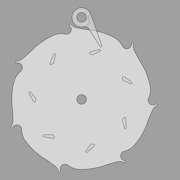
It is unnecessarily complicated, but proves that both parts can be made with a 1mm end mill in a single 3-axis setup.
The tolerances are remarkably tight. If the locking tooth escapes too early then the impulse tooth will arrive ahead of the impulse roller and will interfere with it.
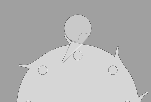
Actually, going back to the pic that shows room for a tiny impulse tooth:
This actually does not show a working tooth, because the impulse tooth will interfere with the forward swing of the impulse pallet, which we can tell because it overlaps the large blue circle.
Needs to be more like this:
And now at the point of unlocking the impulse tooth has still not met the pallet, so the pallet definitely has clearance.
The escape tooth can enter the roller when the roller is at -27.5 degrees. The false entry is about 3.25 degrees of escape wheel motion. The escape tooth can exit the roller when the roller is at +27.5 degrees. The escape tooth is free after moving 12.5 degrees. The impulse tooth is free after the escape wheel has moved 45.5 degrees, and the roller has moved to +82 degrees. The next locking tooth lands when the escape wheel ahs moved to 51.5 degrees.
So:
I can't quite work out the impulse drop because the radii are too large.
I may have to reduce the 0.1mm external radii. In particular the initial engagement of the impulse tooth against the impulse pallet is potentially suspect.
The lock drop is larger than desired. And compared to the reference designs, the unlocking angle is small and the impulse angle is large. That sounds good though: a small unlocking angle means it will run with less amplitude, and a large impulse angle means it will deliver more impulse, albeit asymmetrically.
However what I have here won't actually work because the locking tooth enters the roller too deeply:
Darn. I feel close though. I would want to:
I think the latest I have in duplex-escapement2.FCStd has no geometrical
issues. The unlocking angle is only about 36 degrees, but Daniels
writes about "the inherent disadvantage of the relatively large escaping angle",
so I think it is advantageous if the unlocking angle is small.