Last modified: 2024-01-01 23:01:27
< 2023-12-31 2024-01-02 >This article explains the modern manufacturing process for mainsprings: https://www.thenakedwatchmaker.com/making-mainsprings
It uses a rolling mill to turn the round wire into flat strips.
And this PDF explains the historical process: https://theindex.nawcc.org/Articles/Blakey-MakingSprings.pdf
It has an awful lot of steps and involves a lot of laborious filing and sanding.
So I think my options are:
I actually think it could work with round wire as long as the barrel is made well enough. So I'm going to have a fresh start at trying to make a barrel for 0.7mm wire.
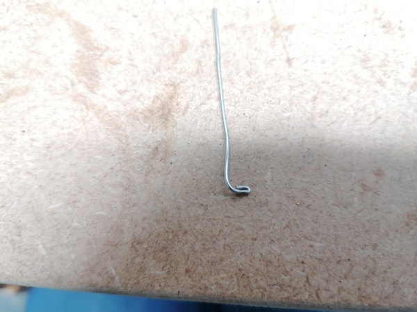
A good technique to tell if the barrel is deep enough is to use a straight edge across the walls and see if the wire fits underneath:
If the wire can be held in place with the straight edge (as pictured) then the barrel is not yet deep enough.
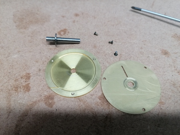
Barrel and cap are made:
Next up, the hub. I recall that last time the hub didn't end up quite concentric with the shaft, so perhaps this time I'll try to make the shaft and hub all in one piece. I'll leave the ends of the shaft at 4mm so that if successful I can potentially turn them down at a later date to suit whatever I want to use this in.
And I didn't like the method of bending a 90 degree hook on the wire to retain it in the hub, because the bend radius makes it bind against the barrel. Need to think of something better.
Maybe I make the hub very large, and have a complete coil inside the hub, terminated with a larger area with the wire looped back on itself, like this:
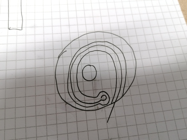
Having two loops of the wire makes it at least 1.4mm thick, so I can safely cut the slot with the 1mm end mill.
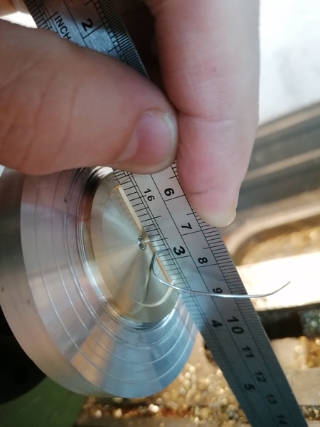
Empirically, the kind of loop on the end that I can make is 3.5mm long and a little over 1.9mm thick. And I can easily achieve a 2.5mm bend radius immediately adjacent to the loop:
We can fit this in a 10mm hub, with 4mm reserved for the shaft:

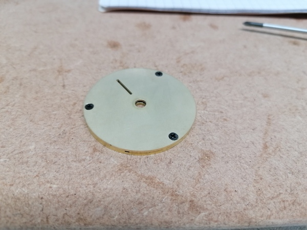
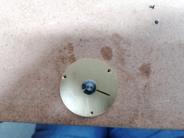
This is what I've got now:
The shaft is a very good fit in the plates, spins nice and freely with almost no play... as long as the screws aren't fully tight. The screw holes do not line up exactly, very frustrating:
They are extremely close, but because the screws are countersunk, they get pulled to the centre of the hole, which binds up the shaft. Maybe I should acquire some M1.6 (or smaller!) screws that have flat heads. Or start making my own screws?
I think the issue might be that when I used the CNC router to drill the screw holes, I didn't get them concentric with the bore to the required degree of accuracy. I've also been opening up the holes, and countersinking them, freehand with a cordless drill, which is obviously fine for getting screw holes to line up normally, but not fine in this application where the screws are pulling the bores out of line.
I'm slowly freeing it up by putting oil on the shaft and running it with a cordless drill, but this is obviously not as good as making the screw holes line up.
I just noticed there are brass witness marks on the shaft, on opposite sides on each end, which suggests the shaft is not concentric. It is possible that the new ER32 collet chuck is not very good! Or that it is fine but the concentricity of a collet chuck is not enough for watchmaking.
I'm going to try to work out a shape for the roller to suit the hook-tooth escape wheel, so as to minimise the drop.
It's not actually obvious how to do this. I think I want to equalise the amount of impulse that is given before and after the line of centres.
So maybe start with the central impulsing point, and mark it on the roller, then advance to the end of the impulse, and mark the contact point on the roller, then revert to the start of the impulse and mark that point, and join them up with a sensible curve. Then go through the whole range again and make clearance for the back side of the tooth, and then see how it looks?
Hmm, not sure. Maybe I just make the impulse face radial, and then plot points to derive the clearance face, and then see if I want to curve the impulse face.
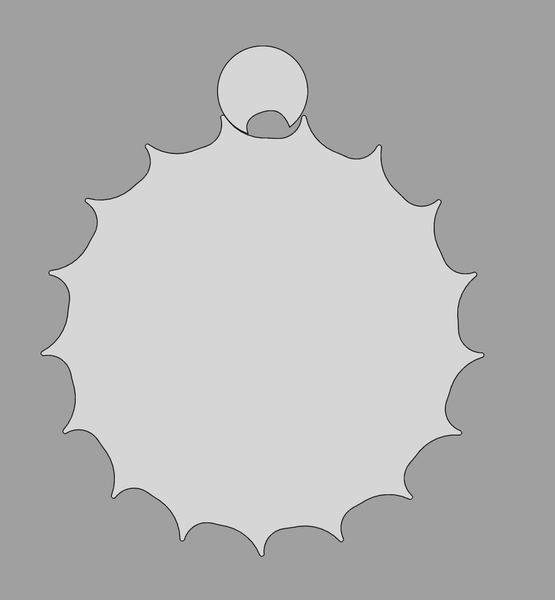
OK, new plan. Keep the impulse face from the previous hook-tooth roller design, but plot points to derive the clearance face. And we get this:
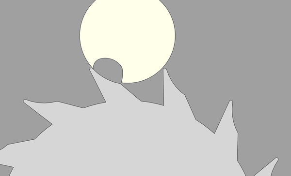
Happily, this can all be machined with a 1mm tool. We don't actually care about the shape of the curve though, as it is mostly clearance. I've marked in red the resting surface and in green the impulse surface:
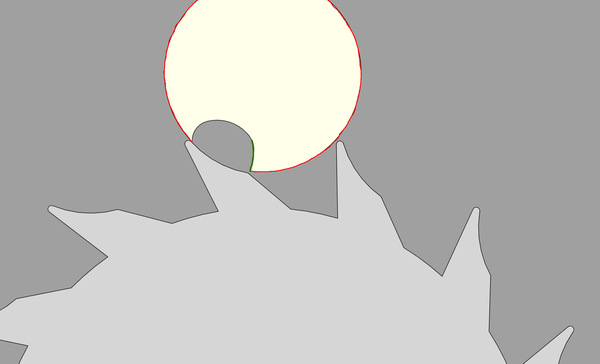
The black surface of the roller never touches anything.
It is probably worth putting a radius at the junction between the impulse surface and the circumference of the roller, to stop it from machining the escape wheel teeth away when re-resting after the "false entry" on the reverse swing.
Things I want to know, which I can probably find out either in a book I've already got or online:
In (the Heskin translation of) "Concerning Such Mechanism", Harrison says:
If such weak impulse was a good thing, then why not apply it at a distance from the centre of motion equal to the length of the pendulum? The impulse could then be reduced even further. How pointless that would be, for the corresponding pendulum amplitude would become so small as to hardly be a motion at all. The property and power of the pendulum would have been lost;
So this seems to favour making the roller radius as small as possible. There's also the fact that the linear distance of frictional rest is minimised if the roller radius is minimised.
I think the downside is that as you decrease the roller radius, you increase the angle through which the impulse is given, and theoretically the impulse should be given instantaneously at the dead point.
Daniels' "Watchmaking", page 195, figure 429, has a diagram of balance wheel rotation showing total arc of vibration of 270 degrees, and impulse angle of 40 degrees.
The quiescent point of the spring is, then, the centre line of the escaping angle.
Daniels, page 196:
During approach to the quiescent point a subtraction of energy will slow the first half vibration, while a subtraction after this point will quicken the half vibration. The remainder of each vibration will be performed in the natural period of the system but the total time of each oscillation will be changed. When energy is supplied to the balance before the quiescent point the first half vibration is quickened while energy applied after this point will slow the second half of the vibration. Again the remainder of each vibration will be performed in the natural period of the system but the total time of each oscillation will be changed.
This makes intuitive sense. If you take energy out of the balance then you are slowing it down. If it's moving towards the dead point then it arrives later. If it's moving away from the dead point then it reverses sooner than it should have so it arrives back at the dead point sooner.
So it is important that the total amount of energy delivered before and after the dead point is equal.
In the roller escapement one extraction of energy is in undoing the "false entry", which occurs after the quiescent point, so this acts to speed up the oscillation. The other extraction of energy is the frictional rest, which occurs everywhere except while impulse is being applied.
The only input of energy is the escape wheel tooth pushing against the impulse face, which occurs both sides of the quiescent point. So we probably want a bit more impulse before the dead point, to undo the effect of the energy lost on the false entry.
How much impulse is my latest CAD giving before and after the dead point? Impulse starts with the roller at -32 degrees and ends at 24 degrees. So indeed I do have a bit more impulse before the dead point, 8 degrees more. How many degrees are spent undoing the false entry? About 39 degrees, but in this time the escape wheel barely moves so the actual amount of energy lost is very small.
OK, so I don't want to be measuring how much of the angle of the roller occurs before and after the dead point, but how much of the angle of the escape wheel occurs before and after the dead point.
Backing out the false entry costs about 1 degree of escape wheel movement. Impulse before the roller is at the dead point comes from about 14 degrees of escape wheel movement, and impulse after the roller is at the dead point comes from about 10 degrees of escape wheel movement. Probably fine? And it can be adjusted by attaching the balance spring differently anyway.
Daniels, page 197:
The desirable basic principle of the radial impulse is contained in the verge escapement
and
The lever escapement has a tangential impulse which is inferior to the radial impulse of the verge.
I think he might be using "radial" and "tangential" in the opposite way to which I understand them. The direction of the impulse force in the verge is tangent to the rotation of the escape wheel, and in the lever escapement it is radial.
Either way, he seems to be saying that he likes the direction of force application in the verge but not in the lever escapement. The advantage is that more of the force goes into the impulse and less into the pivots.
My escapement has a pretty bad force direction when impulse is first applied, it's going almost straight towards the pivot of the balance wheel:
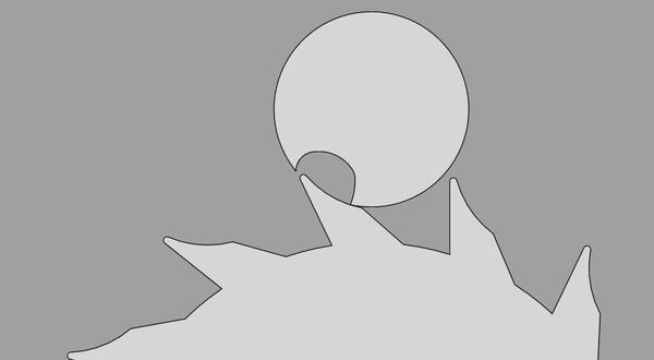
Not really a lot you can do about that though, the tooth needs to enter the roller somehow.
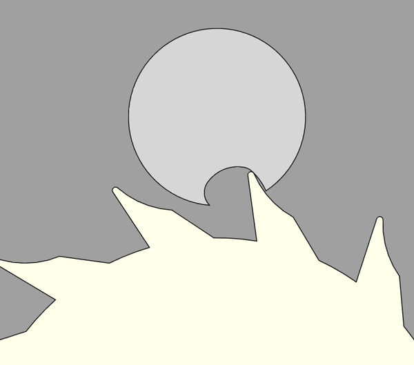
It gets more favourable towards the end of the impulse:
I like the idea of an escape wheel with lots of teeth on it because it reduces the number of teeth I need in the rest of the train, however it is true that escape wheel teeth are much bigger than ordinary teeth, so if I have to put teeth somewhere I should probably prefer to put them on ordinary gears.
But you need an escape wheel regardless, so it may as well have as many teeth as it can take, and if you're lucky you might get to lose an entire extra wheel in the train?
Another advantage of a larger escape wheel diameter is that the impulse vector is closer to the tangent of the roller. There is less work wasted pushing radially towards or away from the pivot.
I want to try making the impulse roller smaller (so that locking & impulse occur closer to the centre of the balance wheel), but keeping the slot basically the same shape, and see how it looks.
By reducing the roller from 5.5mm to 4mm:
So I think this is helpful. And if we reduce it to 3.9mm then we can get a 17th escape wheel tooth.
New animation:
By putting the radius on the front of the tooth, and minimising the size of the opening in the roller, the false entry is kept to a minimum, which means it extracts less energy from the balance wheel on the reverse swing, allowing higher amplitudes.
Previous was:

and you can see there is no "false entry" on the reverse swing, because the balance wheel loses so much energy to the escape wheel that it reverses before it pushes the tooth back out.
Just noticed from watching the "new animation", that we could probably put a radius on the root of the tooth on the trailing edge as well, as there is plenty of clearance and it would make the tooth stronger: