Last modified: 2023-12-31 13:40:16
< 2023-12-30 2024-01-01 >Overnight I was thinking about how to reduce the "drop", mainly so that the reverse swing doesn't lose so much energy. I had a few ideas:
Some of these will obviously be challenging to make at watch scale, but I want to play in CAD to see what I can find.
I've also slightly mushroomed the slot (i.e. the sides bulge outwards so that the cavity is larger, relative to the opening).
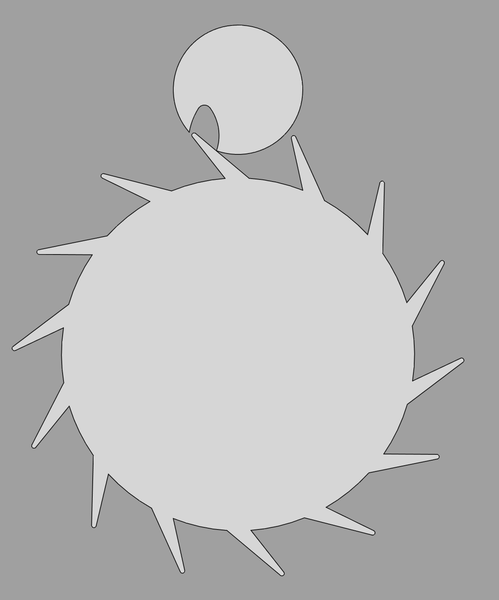
This example (inclined-tooth.FCStd) has the escape wheel
move 1.4 degrees for drop to impulse, impulse for 23 degrees, and then 1.3
degrees to drop the next tooth to frictional rest. It provides
impulse for 66 degrees of roller rotation.
The drop to impulse is 6% of the impulse.
One downside is that due to the undercut, it can't be cut with a fly cutter, so would need to be cut with the CNC router, but the radius is too small.
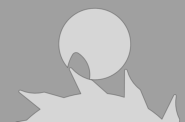
This example (hook-tooth.FCStd) has the escape wheel
move 1.7 degrees for drop to impulse, impulse for 23.3 degrees,
and then 0.7 degrees to drop the next tooth to frictional rest.
It provides impulse for 54 degrees of roller rotation.
The drop to impulse is 7% of the impulse.

You can see that the radius on the tooth is just slightly larger than that of the roller, so that when the tip drops into the slot, the base stops it from dropping too far:
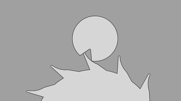
What's the best I can do for a hook tooth that engages with the existing roller? Then I can quickly print a new escape wheel and test it today.
Mmm, not very good. Without the undercut on the slot it binds up:
Let's keep the teeth roughly the same but make the escape wheel 2.5x as big.
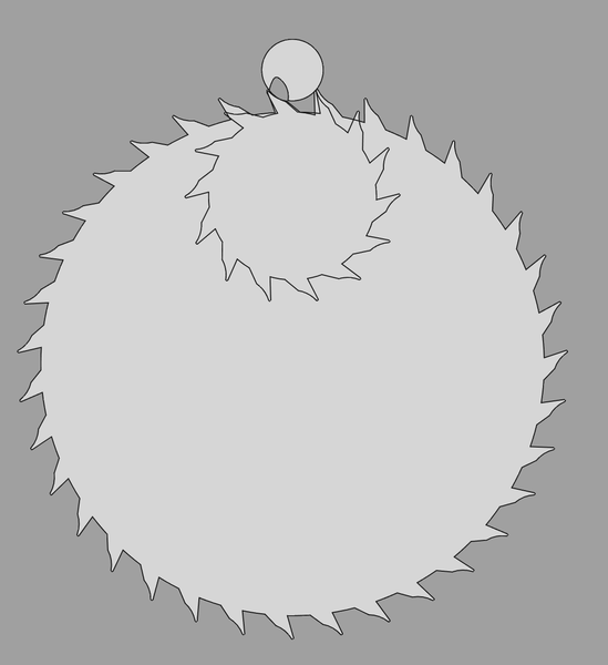
This escape wheel is now about 49mm across, so obviously too large to work. It has 35 teeth. This is up from 20mm across and 14 teeth.
I think it was basically already as large as it can feasibly be, at least without scaling down the teeth and the roller.
Maybe the hook tooth idea is good, but it needs a different roller, so it's slightly inconvenient to test. I'll add a "loose thread" for it, and move on to tidying up and fixing the mainspring barrel.
I've cut a slot in the barrel cap so that I have a chance of seeing what is happening inside:
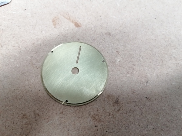
Come to think of it, maybe I could have made a perspex cap just for testing.
Now I'll try to reassemble the barrel, wind it up, and see what I can see. I recall that previously I could put 5 turns on it, then it bound up but I wasn't sure why. I also recall that I couldn't tighten the screws all the way else it wouldn't wind up, presumably the cavity is not deep enough.
Well I couldn't really tell what was wrong. I had to back off the screws to stop it from binding up, but the coils were riding over each other much sooner than expected. Is the cavity depth too inconsistent?
Maybe it would be a good idea to clamp it together with maybe a 0.4mm or 0.5mm spacer inside, to even it out.
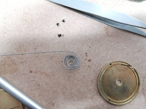
I buggered up the inner end of the wire trying to get it to unwind while it was bound up, and then I tried to straighten it out using the vice and a pair of pliers and I've made a real mess of it. I may have to try a fresh piece of wire.
Well I tried a fresh piece of wire but it birds-nested straight away:
So I think the cavity is not flat enough: as soon as it is open wide enough for the wire to move freely, the loosest spot is open so wide that the wire can easily ride over itself. Mucking about with the perlage (below) can't have helped.
So the next plan is to face off the underside of the cap until there is enough room for 0.7mm wire, and try again. It should be easier to get the flatness within tolerance for the thicker wire.
Ugh, the thicker wire doesn't fit in the hub, and now I've run out of time. I want to look in "Watchmaking" to see what Daniels says about making mainsprings, and then next time I work on this have another think about how I'm going to do it. It may be that I need to get an extremely long piece of thin flat spring, if it turns out that round wire just can't work.
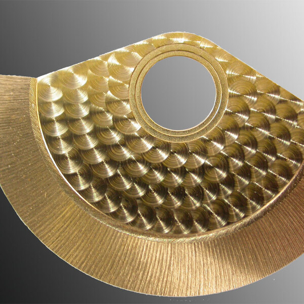
I want to try chucking a dowel in the pillar drill, putting some Autosol on the end, and pressing it against a brass plate to see if makes convincing "perlage". This is what we're aiming for:
This is what I was doing:
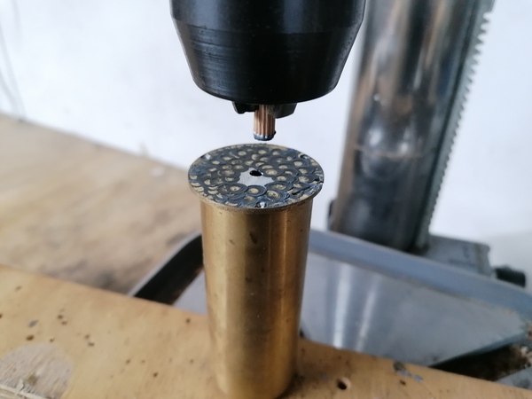
And this is what I got:
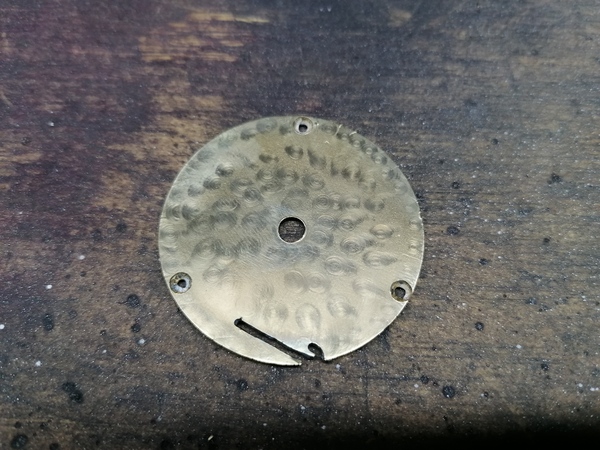
Not exactly what I was after. I'd want:
I managed to dish the barrel slightly because of the cavity in the middle, bad. I've bent it back a bit but obviously don't know how well I've done.