Last modified: 2023-12-31 09:56:01
< 2023-12-29 2023-12-31 >One-way roller escapement model
The plan was:
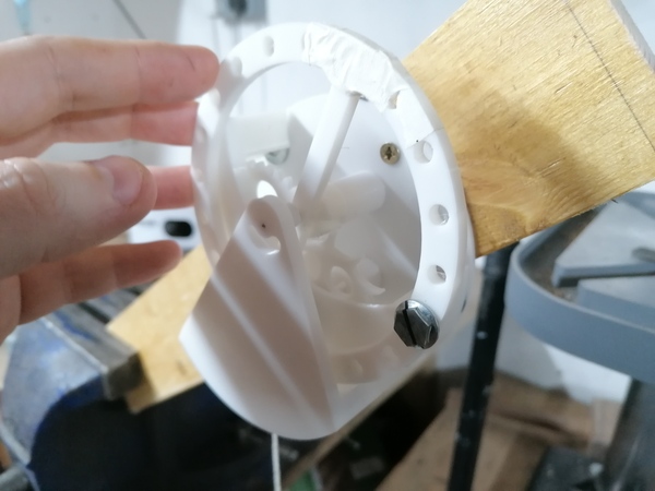
I only made one weight for the balance wheel, just to give it a heavy spot, and apart than that I "poised" it with some masking tape. I put the heavy spot directly in line with the pallet so that the impulse takes place close to the dead point.
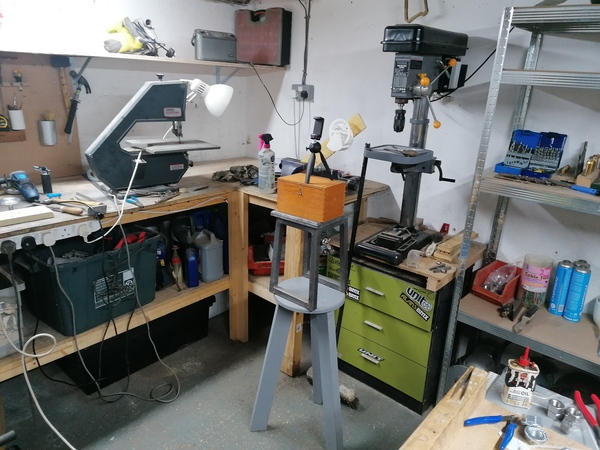
Here's my setup:
First results are:
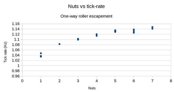
So I think a bit worse than the lever escapement, but a lot easier to make.
Also, I think I should have given it more weight, because the tick rate looks to be leveling out as the drive torque increases. So I will run the same test again but with a static load of 7 nuts, to get data for 8..14 nuts.
It stopped once, while on 12 nuts, but I started it again and let it run a few more laps so that I could get a measurement.
I think the issue is that there is too much friction in the frictional rest. Reducing the size of the roller table would probably help, but I have to bear in mind that I need to be able to make it at a third of this size.
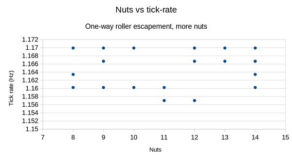
Wow!!
If it weren't for the fact that it stopped once, I would say this is almost ideal.
You can clearly see that the time for one revolution of the escape wheel varied by only 5 frames of video across the entire run, so it's almost at the point where I need to be timing it via the audio track instead of the video.
I didn't have enough of the same nuts to actually add a 7-nut weight, so I approximated it using some different nuts, which could be why it seems discontinuous with the previous graph.
Another possibility is that the mechanism is very sensitive to the angle at which it is mounted. To re-wind the string I pivot the mechanism about its screw and poke out the barrel pivot, but that means when I put it back it is only as repeatable as the Sharpie mark. Although by comparing the footage it looks to be positioned at an almost identical angle in each case. So I'm guessing the discrepancy is due to an error in the mass of my "7 nuts".
This graph almost makes me want to add even more weight just to see how it eventually goes wrong, but I can't be bothered.
I never observed the behaviour where the reverse swing pushes the escape wheel all the way back to frictional rest, which is a shame. Probably the roller table needs to be smaller so that the friction torque is lower.
What I want to look at now is making a software model of this escapement so that I can explore the design space more quickly. It would be good to be able to reproduce charts like the above, showing that tick rate increases with drive torque up to a point, and then plateaus.
Variables in the simulation are:
Simplifications:
One really interesting feature of this escapement is that the frictional rest might actually help, because it means that both the friction and the impulse are proportional to the drive torque, so the amplitude barely varies as the drive torque changes. In the simulation I can change the drive torque through a range of a factor of a million and the amplitude changes by a factor of 2. And the tick rate changes by only 0.2%.
I think it performs so well because of the simplification that all of the friction comes from the frictional rest. And maybe 0.1 is too low for the coefficient of friction.
By holding two 3d flat printed parts against each other and tilting until the top one slides off, I found that it breaks friction at an angle of about 13 degrees. And this was with layer lines against layer lines, in the same direction, the same condition as the escapement. What does 13 degrees mean for the coefficient of friction?
tan(13) = 0.23. So let's say the coefficient of friction is 0.23.
One thing I found in programming the simulation is that the roller table diameter actually doesn't matter, because it gets baked into the "drive torque" value (in terms of the torque that is applied to the balance wheel). I was thinking that a larger roller table would cause more friction, but actually, with the simplification that the torque from the escape wheel is always applied at the roller table's diameter, then the friction torque is always just the coefficient of friction times the drive torque, and the roller table diameter does not actually enter into the calculations, other than that a larger diameter gives more torque.
I plotted this chart:
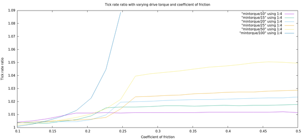
The methodology is that we run a simulation over a range of torque from the "mintorque" number given in the key (in Newton-mm) up to 2x that value, with varying values for coefficient of friction, and measure the ratio between the fastest tick rate and the slowest tick rate.
We see that the error is always minimised if friction is minimised, which is good to know but relatively predictable.
Other questions I want to answer:
I'll do this one first because it's easier.
So that is pretty convincing: you want the dead point around 5 degrees after the point where the escape wheel tooth enters the roller, and this doesn't change much as the drive torque varies.
My guess is that applying the impulse for a shorter angle will give better isochronism, but require more drive torque.
One thing I discovered is that if the tooth never escapes the roller (e.g. because the spring is too strong, or the impulse angle too great), then the balance wheel swings back and forth with perfect isochronism, but this shouldn't count as ticking because it's not actually working.
How do we solve this? Count ticks when the tooth escapes, instead of when the balance wheel crosses 0?
Not sure I've done this right, but:
It looks you basically want to be running on as much torque as you can, and making the impulse angle as large as you can without stopping it from running.
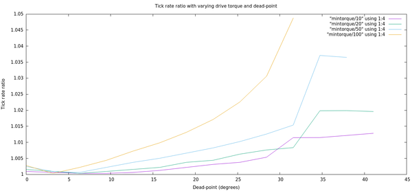
With the tick calculation fixed, maybe I should revisit the dead-point variation.
Ah, indeed:
It's not the case that setting the dead point at 5 degrees is optimal if you want the mechanism to actually work. That was "overfitting" by putting it in a condition where the escape wheel never escapes and the balance wheel just oscillates back and forth against the same tooth!
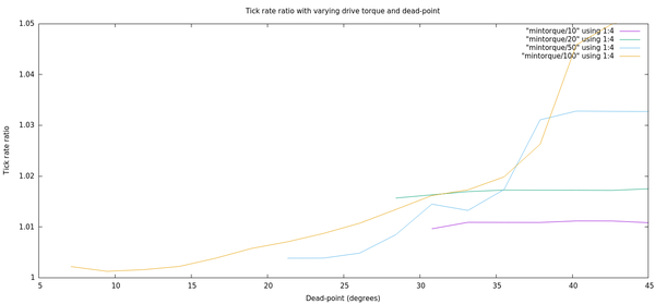
That's with coefficient of friction set to 0.23. What about 0.1?
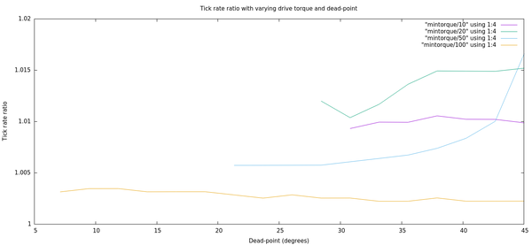
So if friction is low enough it doesn't really matter where the dead point is, but you want to maximise drive torque.
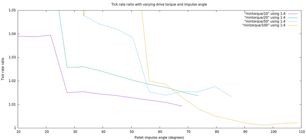
And what if we re-run the impulse angle test, but with friction reduced to 0.1?
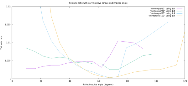
So it looks like the existing value of about 64 degrees is pretty reasonable.
Wait - the bug where it just pushes the balance wheel back and forth without escaping could easily have afflicted the first chart, showing coefficients of friction, so I better do that one again as well.
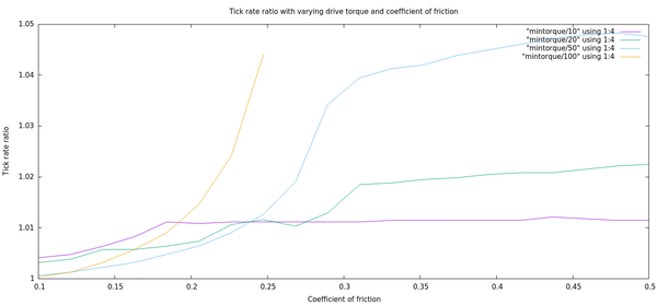
Well it's roughly the same shape as before (lower friction is better), but not quite as good.
Reducing friction makes it work better.
Beyond that I don't really have a lot of insight.
My copy of "Watchmaking" by George Daniels arrived today, and I had a flick through the section on escapements, and discovered the "Virgule" escapement, which seems very similar to my "one-way roller" escapement. Here's a demonstration video: https://www.youtube.com/watch?v=0xKCZnv6118
It is a bit more complex because it tries to make the frictional rest happen at a smaller radius than the impulse, but apart from that is broadly equivalent.
Also I think a better word for "one-way" is "single-impulse".