Last modified: 2023-12-20 17:11:00
< 2023-12-17 2023-12-19 >Let's just make a 3d-printed coil-spring mechanism to turn a hand via a basic runaway escapement of some kind.
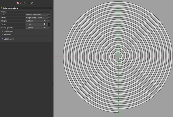
You can make a spiral in FreeCAD by using "Additive Helix" in "Height-Turns-Growth" mode, and setting height to 0, with nonzero radial growth.
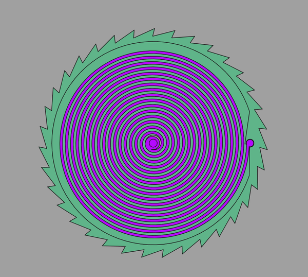
Here's a coil spring:
And a "going barrel":
A click, but I don't like it:
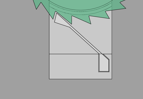
It seems like it will be easy to overpower and turn in the wrong direction.
Good example of a runaway escapement mechanism here: https://www.youtube.com/watch?v=gneCcj1XumY
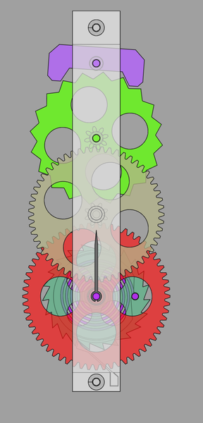
A short geartrain and runaway esacpement:
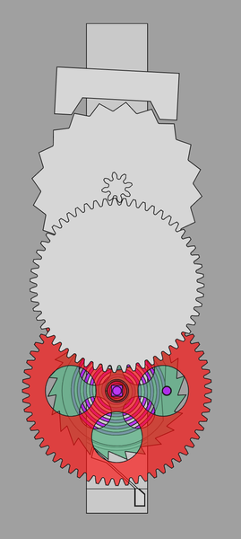
Still need shafts and crossing-out on the geartrain, a pivot on the escapement, a hand, and a front plate for the frame.
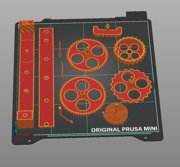
How about this???
Need to check that all the parts will actually print, but I think it should be OK.
Great success:
2h30m to print, I'll start it now.
The stringing was too bad, so the tall thin sections haven't worked:
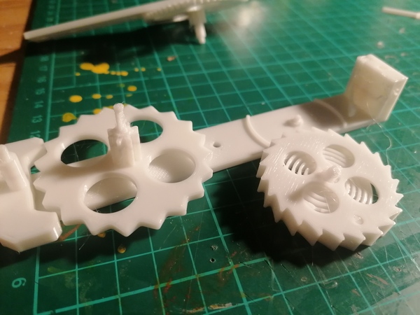
Also the pivots have too much friction so it doesn't work even if I hold it all together. So I probably want broadly the same design, but modified to use steel wire for pivots.
Resuming with yesterday's gear-cutting...
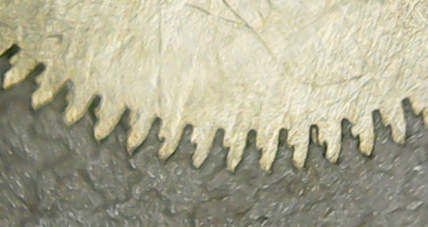
I've finished cutting the teeth to depth, and parted off 4 discs.
I have a new hypothesis about the angled teeth from the previous time: maybe it is caused by the parting-off! The parting tool might be putting so much force on the teeth that it bends them over. So maybe I need to be parting off discs first and then cutting teeth on them.
The tip of the cutter has chipped off again. I think cutting through discs instead of bars would put less stress on it, so that's definitely the approach to use next time. Also it looks like the tip of the cutter is angled down slightly, which could easily explain the angle on the teeth.
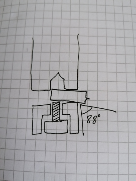
GIMP measures the cutter at 88 degrees from the shaft:
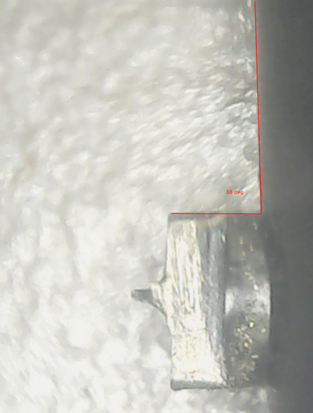
Not really sure what's going on there. Surely the hole isn't 2 degrees away from perpendicular? I'm having real trouble getting the cutter out of the holder, maybe it is bent??
Some of the teeth I made are really bad:
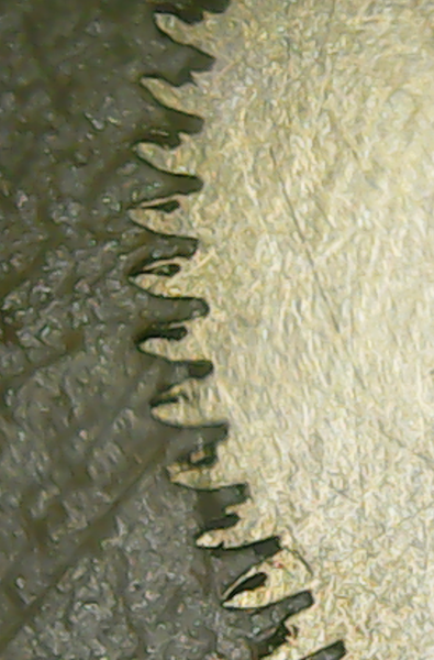
I'm guessing that when I first chipped the cutter and re-made it and re-mounted it, I didn't get it on centre line well enough, so the teeth are a combination of 2 separate cuts not aligned with each other.
I think the issue with the cutter being at an angle is just that it is slightly too short, so the back end of it can fall into the continuation of the M4 hole, instead of clamping nicely against the surface designed for it, like this:
So next up is: