Last modified: 2023-12-17 20:31:48
< 2023-12-16 2023-12-18 >Here's a crazy idea: forget about complicated escapements and balance springs, just use a verge and foliot.
What's the problem with a verge and foliot? It runs faster when more torque is applied. Why? Because the only torques acting on the foliot are the speeding-up and slowing-down actions of the pallets.
If this means that the foliot runs faster in the long arcs, then my idea is that we put some centrifugal weights on the foliot so that its moment of inertia increases when it is spinning faster. We can get some control over the rate at which this happens by putting cheeks on the springs.
And, past that, we could potentially change the geometry of the pallets so that more torque is applied at the centre and less at the ends.
I'm going to write a simulation to see if this looks anywhere near working. I'll start in Perl and if it looks like working then I can change to JavaScript and add a visualisation.
Parts we have include:
As an initial further simplification we can say that the foliot receives a fixed torque towards the centre angle. switching direction instantly as it crosses centre.
Initial impression is that for a drive torque variation of a factor of 5000, the period for 100 ticks (with a fairly arbitrary selection of moment of inertia) varies by a factor of 70 without the centrifugal weights, and with a good configuration of the weights (varying only the mass, initial radius, and spring constant), this is brought down to a variation of a factor of 3. Obviously running 3x faster than normal is no good, but a torque variation of 5000x is also well outside the normal range.
It is possible I made a mistake, and that the factor of 3 is not actually achievable (e.g. if you set the drive torque so high that it always switches from one side of centre to the other in a single timestep, then it looks perfectly isochronous even though it's not).
It is also possible that this required enormous weights swinging at enormous radii. I've tried to make the simulation a bit more realistic to what I could actually fit inside a watch (although even if it is only workable at clock scale, it could be a useful design anyway).
You increase the strength of the centrifugal effect by any of:
It may turn out that even with the masses as close to the centre as you can get them, and as heavy as you can, and with springs as weak as you can manage, the weights don't have enough control to make the balance isochronous under varying drive torque, without having to fly out so far that they wouldn't even fit inside the movement any more.
I'm trying to calculate a configuration that will keep tick rate variation within 1% over a torque range of 10x, and so far it seems to be plateauing around 25% tick rate variation. Maybe need to do more thinking and less brute force search.
It seems to work a lot better if the spring obeys F=k.x^2 instead of F=k.x. I've got it to within 3%
over a torque range of 10x, maybe this idea could work? But I think something is wrong because it is extremely
sensitive to changes like 8 significant figures in.
I'll leave this running but forget about it and go and work on gear-cutting.
It calculated a set of values that are almost within 1% over a torque range of 10x, but it was extremely sensitive to incredibly minor changes. I wonder if the weights are oscillating and it needs them to oscillate at a very precise frequency to cancel out the errors? Maybe I could solve this by making the timestep slightly randomised, or maybe apply a tiny randomised amount of damping to the spring?
Also, just realised that the pallets don't interchange at the centre position, but at some angle after that, otherwise the balance would be able to oscillate in very small arcs around the centre. I did that, and the amplitude just keeps growing. Is that right? We gain a magnitude of 2x the pallet interchange angle on every tick, I think. So I need to add some friction to stabilise it.
OK, another reason it doesn't gain forever is that the decelerating pallet applies more torque as the angle gets further from the centre, as it begins to act closer to perpendicular. The torque it applies is proportional to the sine of the difference between the balance angle and the pallet interchange angle?
Meh, I can't find a configuration that works well enough. I'll forget about it for now.
My small fly cutter holder is ready, I need to make a 3mm round cutting tool for it, let's go module 0.2 again. This time I'll try and work out what I'm trying to do with reference to an involute profile in FreeCAD.
I think the tip wants to be 0.3mm wide, and then the radius wants to be 0.4mm and start 0.2mm from the end? What chance do I have of actually creating this shape manually on the lathe? Maybe give it a go, and failing that, revert to using the CNC router method.
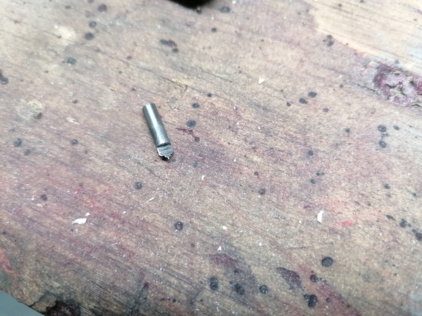
Well I made this:
I did it the way from the Clickspring video, where he uses the lathe to make the geometry, and then machines half of it away, to make like a D-bit cutter.
I'm not sure I've done a good enough job, either of the geometry or the heat treatment, but I'll try it out. And I'm going to use a centre in the collet chuck to zero the Z axis.
The tip of this cutter disappeared almost immediately. I don't know if it was too brittle or too soft. I think maybe too soft, because I could easily file the remainder of the point off. So for my next trick I'll file the point flat and machine a new cutter on the same material, using the CNC router.
One observation is that the CNC method gives much more support to the cutting point, which with the lathe method is only half as thick as its width. I think I did a better job of heat-treating this one.
I tried out using the tapered broaches to widen a pivot hole in one of the aluminium escapement plates, to make the 1mm shaft fit through (just for the practice, not for any purpose). I discovered that I don't have any of the 5-sided tapered broaches suitable for making a 1mm pivot hole out of a 0.9mm pilot. They all either pass all the way through without cutting, or can't fit in to start cutting.
The smoothing broaches are very good though.
I made a quite satisfactory pivot hole, with basically the ideal shape:
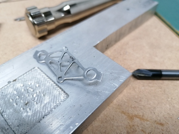
(pic shows oil sink side)
I cut the oil sink with the 6mm chamfering bit, but it pushed a bit of a burr which I had to sand off. I should probably make some sort of oil sink cutter. Do you just want a disc of hardened silver steel stuck on the end of a handle?