Last modified: 2023-10-25 08:35:52
< 2023-10-23 2023-10-25 >First job, design the lid. Then while it's printing I can address cleaning up the bottom surfaces of the cubes, and maybe try to paint the letters.
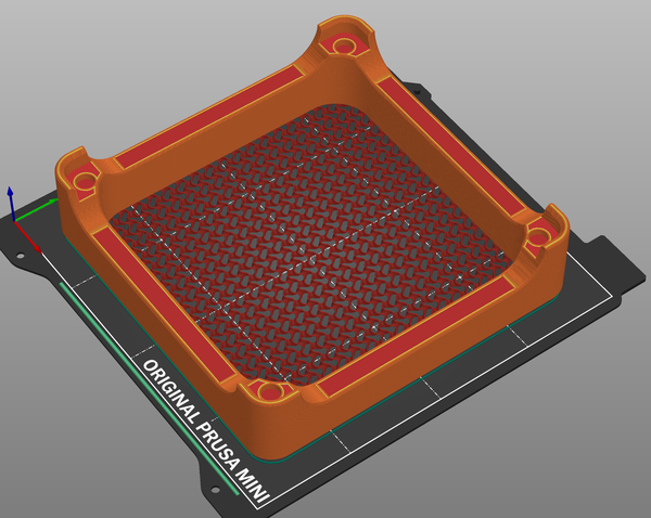
I used a "modifier cube" to reduce top/bottom layers to 0 in the top of the lid:
This is great, because it still lets me have normal solid layers on the rest of it. That's gyroid infill at 20% density. And it's at 80% scale.
I didn't put any branding on the lid, but I left the cutouts so that the writing on the side of the base can be seen.
Plan for painting:
Well...
Not great. Using the thinners on the wet paint didn't seem to be doing anything useful. It just made it more runny (obviously). I plan to let it dry for a bit and then wipe over the edges with thinners to try and clean it up a bit. In some places it has actually soaked through the internal layers, leaving black marks that aren't accessible from the outside, which obviously I can't do anything about.
The paint job is disappointing because it makes the whole thing look much worse. Oh well.
Just waiting for the lid to print and then I can test it out.
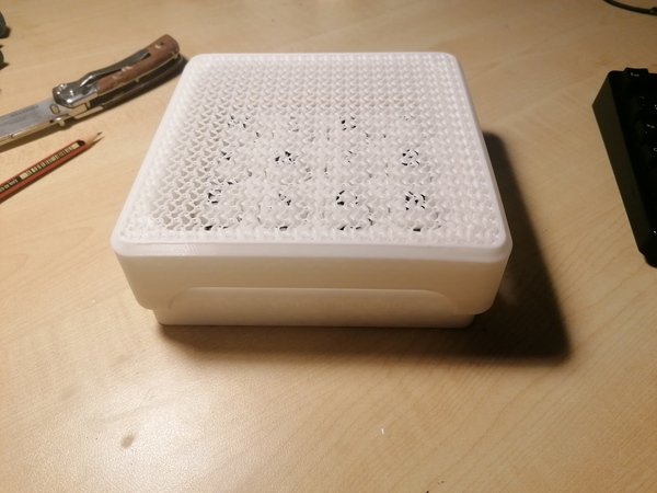
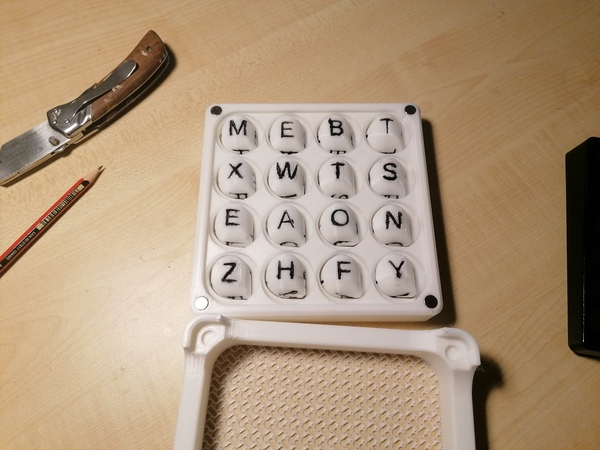
It works really well. It's pretty easy to look through the gyroid infill and get almost all of the cubes seated properly without too much shaking. So I'm happy with this. I don't really see that magnets on the lid are necessary, it's pretty easy to hold it together by hand. I might add some anyway just for completeness.
The gyroid pattern makes a really cool mesh. It is kind of springy, quite satisfying. It is possible to read the letters through the mesh, but it is better than either completely solid (because you can see when cubes are not seated) or completely transparent (because there's at least something to make reading the letters difficult). I'm pretty satisfied with it.
I fitted some magnets to the lid but it's not obvious that this is an improvement over not having magnets. If I share the CAD I'll probably do it without magnet holes.
I wiped all the paint errors with thinners, it made a bit of a difference, still doesn't look great though.
Tomorrow:
I picked up this big stainless box in a charity shop for £5:
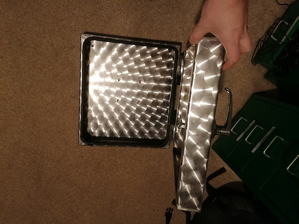
What should I do with it?
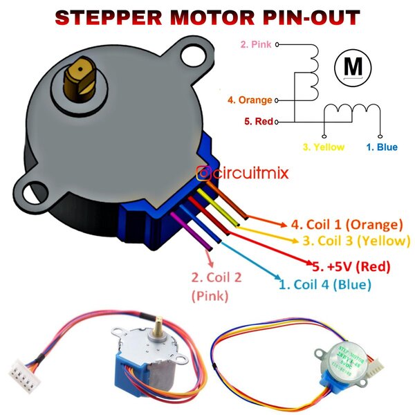
The 6v transformer arrived, and when I hooked it up the motor wouldn't turn in a consistent direction :(. Just doing the vibrating thing. I tried connecting both coils to the supply (instead of just one) and then it stayed locked still, so then I reversed one of the coils and now it seems to work! Great success.
Yellow and pink tied together, orange and blue tied together, red disconnected.
One issue is that it only wants to turn clockwise. Even if I stall it and reverse it, it automatically switches back to clockwise. This is a problem because I need it to go anticlockwise.
Let's see if using the red wire can help? Swap the pink/yellow wires for just the red wire. This might result in more current flow, but going through less turns of coil, which should be a no-op but let's see?
Just buzzing and not turning.
What if we go back to the 12v transformer, but instead of having pink/yellow and orange/blue in parallel, we make it go pink -> orange -> yellow -> blue? So we only have 6v across each coil? Oh, hang on, this won't help because the coils are shorted together at the halfway point anyway, because of the red wire. I'll try it anyway.
Yeah it makes no difference whether I connect the orange/yellow pair or not. At least on 12v I can get it to run in both directions, but it does get quite hot. Actually it does have quite a strong preference for clockwise. That's annoying because that is the exact opposite of what I want.
I could conceivably mount the motor the other way around (on standoffs) so that it can be allowed to turn clockwise.
I think to minimise heating the best option is to run it on 6v with the two coils wired together, and mount it on standoffs so that it turns in the right direction.
I wonder why it prefers clockwise? I don't think it did at first, maybe just because the gears have run in. If I forced it to turn anti-clockwise for a while would it lose its preference? I messed with it a bit but couldn't be bothered doing it for long enough to make any difference.
I'm going to leave it running for a bit to see how hot it gets. I expect not very.
Update: it has got a bit warm and now it has stopped turning :(. So maybe the answer is to use 12v and put a heatsink on it.
I'm back on 12v now, running it with only pink and orange connected (i.e. using just one coil). It is again happy to run in both directions, I've set it going anti-clockwise, will see what happens as it heats up. I've left it sitting on an aluminium heatsink.
It gets hotter than I am comfortable with. It is too hot to hold onto for more than a couple of seconds. I've put it on the die block now. If it heats the entire die block up to this temperature then I will probably have to think of something else.
This has actually cooled it down quite well! Not sure how long for though. If it stays cool long-term then I'll just mount it in the clock with a big heatsink. I don't know if this is stabilising at a lower temperature because of the extra surface area, or if it is just taking a very long time to warm up because of the extra thermal mass.
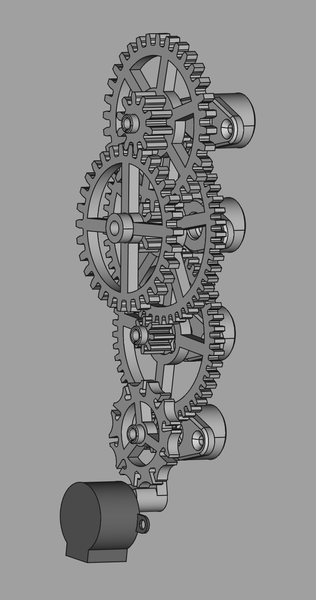
I think I'll just stick a block of aluminium to the back of the motor and have it radiating up the back of the clock. It needs some clearance at the back anyway for the ends of the shafts. Plus if I make room for a heatsink then I can make the bearing blocks longer which will make the shafts more stable.