Last modified: 2023-10-20 01:24:29
< 2023-10-18 2023-10-20 >I was thinking if I make the "OpenStreetMap Viewer" thing, then I should have a cool way to present the Bangle.js data with several routes loaded up at a time, and coloured according to the delta time.
Not sure whether each segment should be coloured according to the delta time of the route up to the end of that segment, or just the change in delta time (delta delta time?) during that segment. Maybe both options.
You might be able to identify "critical areas" by which areas have the highest variation in delta delta time.
I wondered about bolting on one of those pieces of aluminium hub offcuts and making the chuck register out of aluminium, might get a better register because aluminium is easier to cut? Or maybe I should just try re-cutting the steel one again now that I've tightened up the machine a bit. And run a lot of spring passes.
I feel like I've got better at both designing things and making things since I was last looking at making a self-aligning Boggle board.
The latest was in https://www.youtube.com/watch?v=pbfjU9Zkcgw
I conclude "it doesn't look like this idea is going to work, so I'll have to come up with something else". But looking back at it now, I actually do think the idea is sound.
What about some combination of these ideas:
The roots of the teeth as designed are about 1.4mm, so I could potentially finish these with a 1mm end mill. The grooves in the tiles are 2mm across, which isn't a problem either. The only thing that makes it annoying to machine is the amount of work.
16 cubes with 6 faces each = 96 faces.
What about starting with a 20mm x 20mm square bar, 350mm long or so, and do 16 faces on the top, then rotate it 90 degrees and do the next 16 faces, and so on, to get the first 4 faces done for each cube in only 4 operations. Then cut them all apart, and then what? 32 more operations?? And how are you rounding all the edges? Maybe use a round-over bit, then you can do it from above. It currently has a 13.4mm radius, which is an annoying size, but could be redesigned to use a sensible radius.
And you can do all of the round-overs in the initial 4 operations.
Maybe you'd have a fixture that can clamp several cubes at a time.
Maybe machining it is too much trouble.
So then options are:
It is only 120mm long at the moment, and the printer can fit 180mm long, so it could easily be 50% bigger without even having to CNC anything. There's really no downside to making it bigger. And the advantage of keeping it 3d-printable is that I can make more than one without too much trouble.
OK, OK, how about this.
Each letter spot is a full-on cylinder, to the full height of the letters. You somehow mix the letters up separately, and then have a tool that smooshes them about so that one goes into each cylinder, and presses them in to the bottom. And then the rotation is done by pressing on the sides of the tiles, instead of the bottom. So all the edges would be rounded apart from one.
In fact, do the cylinders even need to rotate? What if you make the cylinders have a helical notch around the outside, which catches the tile as it is dropped in and automatically spins it as it falls? Doesn't actually seem possible.
What if the thing you smoosh it down with has the alignment feature on it, and you keep shaking and smooshing it until it presses all the way down? Would definitely work for 1, but 16? Maybe the alignment feature is spring-loaded separately for each cube, so that once it is in place the shaking can't take it out of place?
Maybe we just need something to make the cubes rotate but that will allow them to drop into their cylinder once aligned correctly. So then you'd first shake the cubes up to randomise their order and orientation, and then something would make them rotate until they align with their hole, at which point they fall into the hole.
Can you make a funnel shape that will automatically direct the pointy bit towards its notch as it falls? Maybe that would be too far outside the realms of 3d-printing even if you could.
I wonder how effectively they would get pushed into the right places if you just pushed them in by hand while shaking? Maybe that's a prototype worth making.
You could imagine a spring-loaded rotating plunger above each cube, where they all rotate with a geared mechanism like in the prototype, but that is over-complicating things I think.
Given that each cube will have 3 sides that are rounded, can we separate all of the rounded sides, so that whatever orientation it lands there is always one that's close enough to the notch in the cylinder that it just falls straight into it?
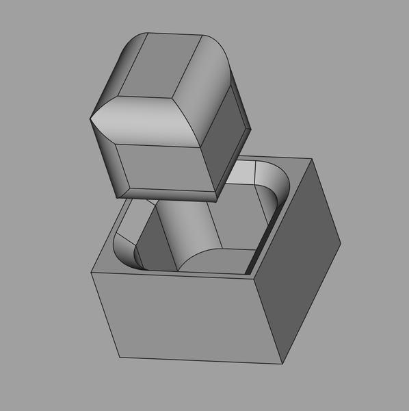
Here's the kind of thing I'm talking about:
OK the "cylinder" part isn't very cylindrical. We have a nice vertical rectangular face to put the letter on. The letter doesn't have to be centered in the "cube".
Or an even more extreme shape:
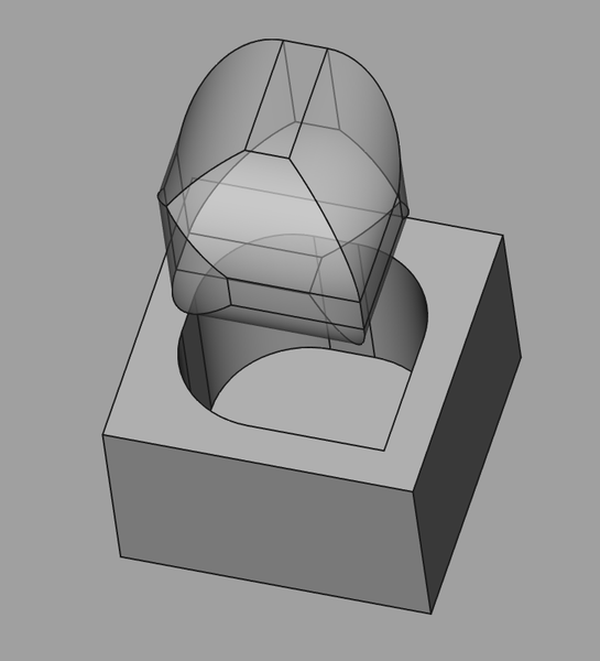
The letter can "sink" into the radius if it has to. The question is: will this shape self-align with the hole, if jiggled?
What about this as a tester?
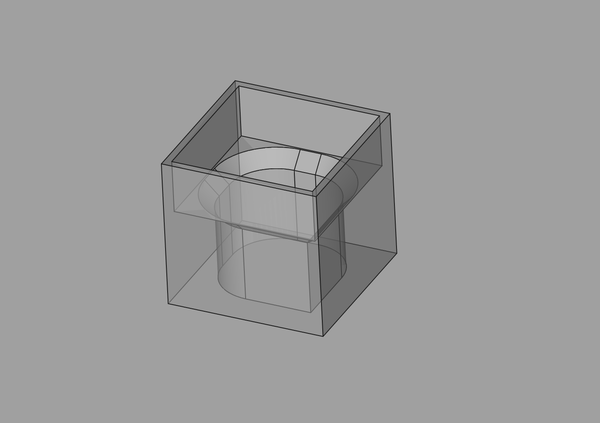
I can sit the "cube" in the top, and shake it, and see if it falls in. And if it does then we're golden. The base is then a piece of piss to CNC (albeit with a little radius in the corner). And then CNC tiles would be nicer, but 3d-printed ones would be easier... The age-old conundrum.
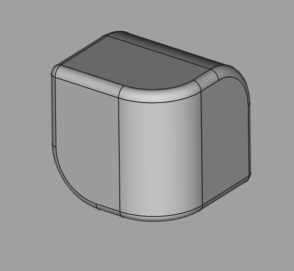
Is the chamfer around the rim helpful or harmful? It might actually be better without the chamfer, if that causes the cube to "tip" into a better orientation? I'm just going to print it with the chamfer and see how it feels.
It would be cool to make the outside profile of the base have the same shape as the pockets.
Verdict: it doesn't work very well :(. Sometimes even quite a bit of jiggling isn't enough. It sometimes gets the "poles" (the 2 points where it's rounded in all 3 directions) stuck across the sides of the hole. I don't know if rounding these off further would help or not. It's possible that rounding it off further would just allow it to get deeper in an incorrect orientation. For this reason maybe the chamfer is undesirable.
I wrote some letters on the faces so I can more easily see how close it is to correct alignment, and it seems like it often doesn't slot in even when it's almost exactly correct.
So, some ideas:
I've carved the points off the "poles" and actually I reckon it has helped. I wonder how well this would work if the rounded edges were chamfered instead of filleted? Probably not as well. And carving the rest of the sharp edges down a bit seems to have helped as well. So maybe "secondary fillets" is the answer.
I tried oiling the rim of the pocket to see if that would make it rotate more easily but if anything it seems worse. Maybe the friction is important for making it bounce around.
I think the whole problem here is balancing making it easy for it to slide in when it's almost aligned correctly, vs. making it hard for it to slide in when it is not aligned correctly.
What if instead of 3 rounded sides and 1 pointy, we had 3 pointy sides and 1 rounded? This is also way easier to model, and (getting ahead of ourselves) would be less cuts on the CNC.
Would this work better or worse? I think the idea behind making it mostly rounded is that round things rotate more easily.
I noticed the poles always need to end up in the same places. If "front" is closest to us, then they are at front left on top and back right on bottom. So if the poles end up anywhere else, what we need to do is shift the poles into these positions.
Can we imagine "stretching" it along the axis that the poles lie on, so it's a bit like an airship shape, and then it needs to rotate so that one end of the airship can drop into the back right corner, and then rotate so that one letter face points up.
Rotating it around the poles gives you 3 different letters, and then swapping the poles end-to-end gives you the other 3.
If the poles "stick out", then we need to make it slope "down" towards the locations that the poles need to be in, and then the poles are most likely to get directed towards the right places. But actually I think (with the current version I have made) the poles stick out less than the rest of it. This is the benefit of the "3 pointy 1 rounded" version - in that one the poles actually do stick out the most.
This page has some good stuff on automatic component alignment in manufacturing: https://us.misumi-ec.com/blog/component-alignment-technology/
A cube sits flat automatically because it is unstable in other orientations. But how do we design a housing for a cube-like object that will cause it to be unstable except when facing the correct direction?
Definite improvements to make:
Interestingly, the cubes can be either right- or left-handed based on whether the pole axis runs through bottom front left or top front left.
In this order:
mk-pivot onto the milling machine PCObviously won't get to the end, but then copy the list over.
< 2023-10-18 2023-10-20 >