
Last modified: 2023-10-14 21:36:06
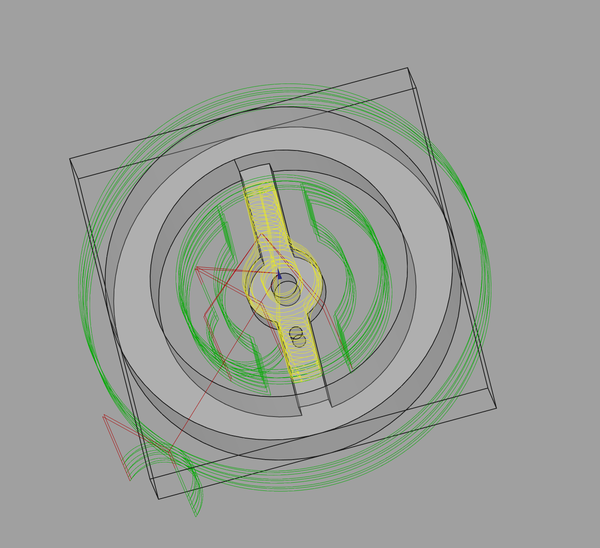
< 2023-10-13 2023-10-15 >The toolpath it generates looks like this, from the end:
I'm not sure if I should be concerned that the "middle" ring of lines there doesn't appear circular? Need to try it out and see how it looks. Is the trigonometry wrong?
Well I got this:
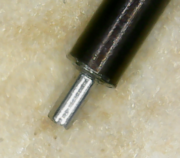
Looks quite good! Better than the previous attempts. The shoulder looks tapered in that microscope pic, but with the loupe it doesn't look so bad.
The concentricity is not perfect but is better than before.
One issue is that the rotation speed of the A axis is really slow during the cut. I think it is because the 30-degree angle increment means it maxes out LinuxCNC's look-ahead before it can reach the programmed speed. Bit annoying, but not the end of the world.
I am going to keep using this method of making pivots for the time being, not least because it is really the only way I have to make them anywhere near concentric, given my homemade 1mm collet.
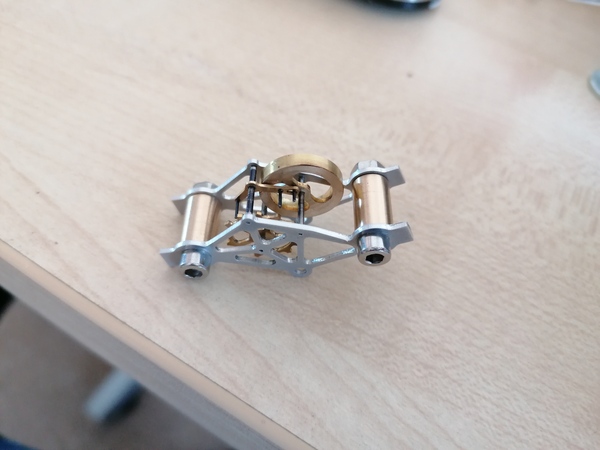
Let's try and make a balance wheel next.
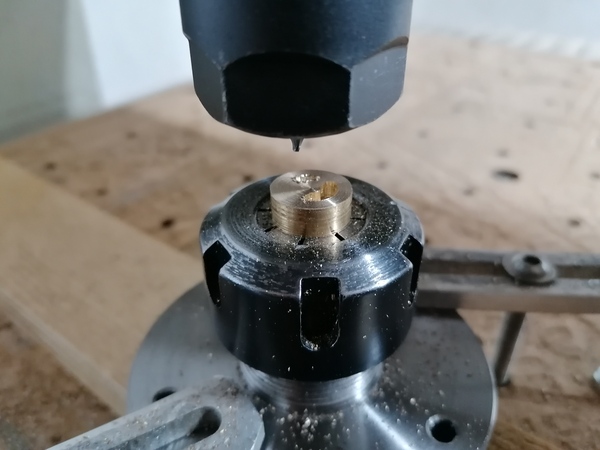
I'm using an "adaptive" strategy for the bit in the middle:
With 2mm tool, 150mm/min feed, 50% stepover, 0.5mm stepdown, 1.5mm final depth. Not sure if this will take too long.
The tool broke before I even got to the adaptive part.
So maybe 0.5mm stepdown is too aggressive for it. I don't have another 2mm tool sadly. I have some 3mm ones, I'll try the same feeds and speeds but with a 3mm tool, and tidy up the internal radii with 1mm if I'm not happy with it.
I've ordered a packet of 10 replacement 2mm 1-flute tools from Amazon for £15. Not sure if that is a wise investment, but Rennie Tool is out of stock of up-cutting 2mm 1-flutes, so worth a punt.
Update: I used 50% feed override mostly, because the 3mm tool was down-cutting. I also used a low-pressure air blast from the compressor, which worked so well I can't believe I haven't been using it before. I need to rig up something to hold an air nozzle so that I don't have to do it by hand.
Making the balance wheel was the same procedure as before: machine it, drill the holes, part off, superglue arbor, face to length, sand, clean.
I haven't polished this one (yet?) as the faces are too difficult to get to.
The process for these parts is pretty reliable. Very good. The worst part is probably the bit where I have to burn the superglue off, I always feel like I'm damaging the surface finish, both with the flame and with whatever tool I use to see if the glue bond is loose. Maybe I need some soft but heat-resistant tweezers?
I'm going to use the test pivot from mk-pivot earlier for one end, but cut the piece of rod to 12mm length, and use
mk-pivot again to put a pivot on the other end.
The shaft itself was fairly straightforward, although I am having trouble with:
So maybe I need to just accept that glue will be required and the press-fits are not adequate. Maybe I need to go to the trouble of chucking the pins in the lathe and turning to length. And maybe I need to make some special fixtures that let me tap the shafts into the correct positions.
Also, I managed to twist the frames while trying to undo the bolts without using the vice :(. Sad times.
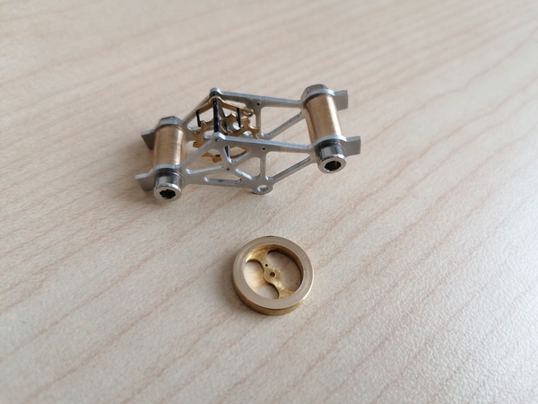
The impulse pin fits in the pallet fork slot, and the balance wheel and pallet fork interact nicely, so that's good!
But I have the axial positions all wrong, so the pallet pins don't engage the escape wheel. And there is also nowhere near enough room for a collet/hairspring.
But this is some progress.
Print out some sort of technical drawing showing the axial locations on all the shafts, lengths of pins, etc., and then write instructions for making:
The China transformer arrived. I plugged it in and it did not blow the fuse, great success. And the output measured at 13v AC.
I connected it up to 1 coil of an ex-3d-printer stepper motor, but the stepper motor just vibrated randomly instead of turning in a constant direction. I tried connecting up the 2nd coil as well, with both polarities, and it did the same thing. I think the issue is that 50Hz is too slow, so the stepper motor always stops, and then is in the "restart in random direction" mode.
So I need to try out the cheaper, nastier stepper motor, on the basis that it travels further with each step and might work better. Failing that I need to try to work out how to delay the waveform by about 90 degrees.
The cheap and nasty stepper works! Great success. I was using the pink and blue wires. And it does indeed reverse if it stalls, so a ratchet would do the job.
The motor is labelled "5VDC", but the transformer is giving more like 13v. The motor is getting a bit hot, but so far not excessively so. It buzzes a bit more loudly than you would want in a clock.
I tried powering it through a 150ohm resistor, and not only did it work, it was now much quieter, and it would only go in one direction (???). But the resistor got extremely hot, I'd need a power resistor instead.
Maybe instead of a resistor, I use the scary transformer from yesterday to step 13v down to something lower. Doesn't work, gets less than 0.2v on the secondary.
Maybe I should take the transformer apart and take half the turns off the secondary so that it gives me half the voltage.
A 28BYJ-48 apparently has 64 steps per rev, which means it should do a turn in just over a second, maybe? But it seems to take more like 10 second, is there a gearbox on it? Lol, apparently they are all sold with different gearboxes, and some of them don't even give you an integer number of steps per revolution. Such fun.
It did 10 turns in 102 seconds. I don't know if one AC cycle is 1 step, 2 steps, or maybe 4 steps because only one coil is in use?
1 turn in 10.2 seconds corresponds to 1 turn in 510 cycles. Which could be 510, 1020, or 2040 steps. There is evidence online of someone who has measured one of these at 2037.5 steps per rev, so we may be the same as that one. But someone else says 2048 steps per rev. I'd probably want to set up an Arduino to do thousands of turns at different step counts and see which one actually ends up pointing where it started.
Let's measure it again but with more precision on the timestamps.
The DuckDuckGo builtin stopwatch looks pretty decent, has a lap timer and 2 decimal places of precision on seconds.
It took 6m50.46s to do 40 revolutions. From eyeballing the times, it looks like the seconds are precise to better than about 0.1s.
So it might have been 6m50.36s up to 6m50.56s. What steps/rev would they imply?
6m50.36s has 20518 steps, and 6m50.56s has 20528 steps. But multiply by 4, so 2051.8 up to 2052.8 steps/rev.
I found this page http://arduino.dansetrad.fr/CoursPasAPas/28BYJ-48_Adafruit_5V_2052.pdf that reports 2052 steps/rev exactly, which is within my proposed range, although it's not clear how exact that actually is, because it also says there are 32 steps per rev of the motor and a 64.128x reduction, but 64.128 * 32 = 2052.096.
So is 64.128 an approximation, or is 2052 an approximation, or maybe both? But from this information I reckon it is between 2052.0 and 2052.1. But that is potentially an error of 4 seconds per day, so I need to know to better precision than this.
Ideally I would open it up and count the teeth on the gears, but it is sealed a bit too well, I'm not confident I can get it apart in a way that will neatly go back together.
Ah, I could try and come up with plausible systems of gear ratios that result in steps/rev around 2052, to rule out any that seem impossible. The guy on the Arduino forum at https://forum.arduino.cc/t/28byj-48-steps-per-revolution/876716/2 said
Mine is 32/9x22/11x26/9x31/10 = 64 x 403/405 = 63.68:1
We can take the 32 for granted, then DFS sets of 4 gear ratios with sensible numbers of teeth to find results between 2052.0 and 2052.1 steps/rev.
If:
Then these are the only possibilities for the ratios:
64.1262002743484  32:9 26:9 29:12 31:12
64.1255886970173  32:9 27:13 37:14 46:14
64.1259777259777  32:9 29:11 29:13 46:15
64.1255886970172  32:9 37:14 27:13 46:14
64.1271794871795  32:10 22:10 29:12 49:13
The first one has the least extreme tooth counts, so I'm inclined to suggest that that is the most likely one. But the PDF did say a ratio of 64.128... What would it take to find a ratio of exactly 64.128?
Even if I allow 8..18 for the pinions and 8..50 for the big gears, there is no solution for exactly 64.128.
Oh, actually we can't take the first 32 for granted, because it's actually the number of teeth on a gear, not the number of steps per rev of the motor.
If we relax that requirement, and restrict pinions to 9..12 and big gears to 20..35, then we get only:
64.1262002743484 20:9 26:9 29:9 31:10
Which is the same ratio as the one I thought was likely before! Albeit with a different set of gears printed. I just remembered that it doesn't re-print the same ratio with different gears, so I was wrong to discard the ones with extreme tooth counts (because they could have been shadowing an alternative arrangement with more sensible tooth counts).
Let's assume that this is the correct ratio. So I get one revolution every 186992/18225 = ~10.26019204 seconds. So 1 hour is how many revolutions? (3600 * 18225)/186992 = 4100625/11687 = 350.8706255.
So now what? Do I repurpose my perl script to try to find an exact solution for that, out of sensible gears?
Do I butcher the top off this stepper motor and make some replacement gears with a more useful ratio? Could skeletonise the housing while I'm at it. No, let's keep it simple. I want to design a clock around this motor that I can build in a single day.
The easy way is probably to manually invert everything that is inside the stepper motor until I get to something turning at 50 teeth per second in sync with AC, and then gear it for minutes and hours.
< 2023-10-13 2023-10-15 >