Last modified: 2023-10-15 19:36:13
< 2023-10-14 2023-10-16 >Stepper motor clock gear ratios
So I think the ratio of the gearbox in the stepper motor is 46748/729.
If I'm wrong, then from the timing measurements I did yesterday, it's at least within 4 seconds a day. A clock needs re-setting every 6 months, so it could drift by up to 180 * 4 = 12 minutes in 6 months. So not really the end of the world even if I have got it maximally wrong.
At 2052.0 steps/rev it would take over 2 days to do an extra revolution compared to 2052.1 steps/rev. So I know that if I run it for less than a day I won't miss any extra revolutions, so I can just grab a high-resolution start time, wait less than a day, and then grab a high-resolution stop time when it completes the next revolution, and I'll know that I can divide by about 10.26019204 seconds to work out how many revolutions it did, and then work out exactly how long each revolution took by working out which one lines up with the exact stop time. Does that make sense?
Well I tried it and it came out saying about 111.5 rotations. Not good...
Maybe my time measurement yesterday was not as precise as I thought (maybe
the DuckDuckGo timer is not very good?). I'm using Time::HiRes now with
a custom script.
I'll take a bunch of lap times and see what it looks like after a small number of laps, same as yesterday.
15 laps in 153.435 seconds = 10.229 seconds per lap. Lol. Yesterday DuckDuckGo worked it out to between 10.259 and 10.264. What is up there? Let's try again with DuckDuckGo.
DuckDuckGo gets 13 laps in 133.34 seconds = 10.257 seconds per lap.
So this is crazy! What is going on? Is DuckDuckGo gaining time with every click? Is it the thing where browsers don't expose high-resolution timing as a security precaution? If I let it do 13 laps in DuckDuckGo without clicking the lap timer each lap, what do I get then?
13 laps in 133.28 seconds = 10.252 seconds per lap.
And what if I try again with Time::HiRes?
13 laps in 133.05 seconds = 10.235 seconds per lap. What is going on?!
Let's try another online stopwatch. https://www.online-stopwatch.com/
13 laps in 132.93 seconds = 10.225 seconds per lap. So it looks like only DuckDuckGo is wrong. Let's try and debug that.
Well the JavaScript looks perfectly reasonable.
function updateStopwatch() {
    var t = new Date().getTime() - start_time + old_time;
    $total_time.html(formatTime(t));
    $current_time.html(formatTime(t - last_lap));
    return t;
}
function addLap() {
    if (!running) return;
    var current_time = updateStopwatch();
    ...
So what could possibly be the issue here? I'm going to run Time::HiRes
and DuckDuckGo simultaneously (but 1 lap offset, to give me a chance
to operate the buttons) to see what they say.
DuckDuckGo: 18 laps in 183.89 seconds = 10.216 seconds per lap.
Time::HiRes: 18 laps in 183.81 seconds = 20.212 seconds per lap.
So at least they're pretty much agreeing now, but I'm surprised there is so much variation. Is my PC clock not very reliable?
The time from earlier was some integer number of revolutions in 1319.06 seconds. We get:
So let's say it's about 10.225 secs/rev. But yesterday I measured 40 revolutions in 6m50.46s, which should have actually taken 6m49.00s if it's only 10.225 secs/rev. I can understand being a bit off, but a second and a half?
Possible hypotheses:
I'm going to leave it running with Time::HiRes timing it and see
what happens.
In other news, I have confirmed that it is about 32 steps/rev of the internal stepper, by clicking the "lap" button on the DuckDuckGo stopwatch in time with the pulsing noises, and it comes out at about 0.64 secs/lap, which corresponds to 32 steps at 50Hz.
Well I've come back to look at the Time::HiRes data, and... it looks
like it doesn't turn at a consistent speed? Maybe the stepper motor is
losing steps? But if it were actually stopping, it would sometimes randomly
reverse, so that doesn't seem likely. Maybe the PC clock is just not
very good?
Maybe the gears are made very poorly so it actually turns at different speeds depending on how the gears are aligned?
Keep running it for longer and see if it converges.
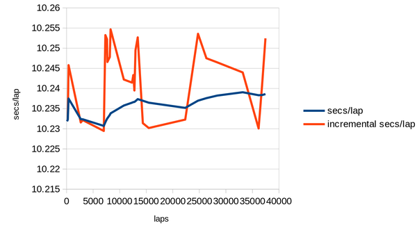
Update: it might be converging to 10.24 secs/rev exactly, which is in fact the nominal specification of these motors.
I plotted the implied secs/rev numbers from the data points I've gathered:
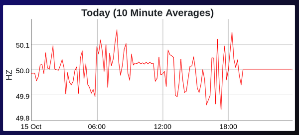
It looks like there is kind of a "fast" set and a "slow" set of the incremental data points. Maybe this is caused by the grid varying between 49.9 Hz and 50.1 Hz to try to maintain the average?
Is there some data source showing recent grid frequency? I really need to build that mains electricity datalogger.
https://gridwatch.co.uk/frequency - this does actually show that it has varies between 49.9 and 50.1 in the last day!
Probably I should leave the stepper motor running overnight and see how it looks in the morning. The issue is that if I leave it too long I won't get very precise counts of the number of revolutions.
Firstly, I want a technical drawing showing the axial locations of each part on its shaft.
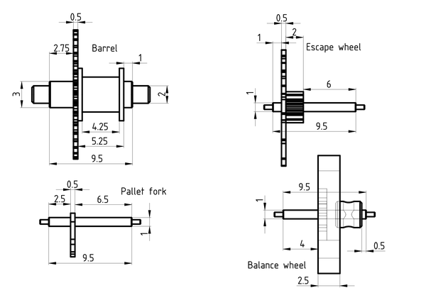
It shows some diameters as well, but it has most of the axial positions that I care about.
And then, instructions for making:
Ideas for this include:
I quite like the idea of a hole with a precise depth. It can be 1mm deep to the required axial position, and with a 0.5mm hole in the floor for the pivot to sit in, so that the load is taken by the shoulder instead of the pivot. And we want a staking tool, also with a 1mm hole up the middle, to hammer the wheel down with.
So I probably want to drill 1mm (1.1mm?) holes into the die block, with depths:
And with 0.6mm (oversized) pivot holes in the bottom.
And once the pallet fork is on its shaft, then how do we fit the pallet pins?
Coincidentally, this video was released today: https://www.youtube.com/watch?v=PAFBkgawH3w&t=230s which at 3:50 shows using a hollow tube in the tailstock to press something on using the lathe, pretty good idea.
The problem might be that because of the tapered reaming, there is actually only a very small piece of brass in contact with the shaft. This may also be the source of the perpendicularity problem.
Maybe I drill a 2.5mm deep hole in the die block and grind/file the pin until it is flush with the top?
Maybe I hold the pin in the pin vice and grind/file it until it is the desired length?
If the shaft is in a hole and the wheel is tapped down to a perpendicular face, maybe that is enough?
So here's the plan for how to get everything together properly:
Take all pins and shafts out of the parts they fit.
Cut the pallet pins (2.5mm) and impulse pin (3mm) to the correct lengths, using the pin vice to hold them. Deburr the ends.
Drill (slightly-oversized) 1mm holes in the die block to 4mm, 6.5mm, 8mm depths. At the bottoms, drill (slightly-oversized) 0.5mm holes to let the pivot pass through.
Engrave next to these holes to say what depth they are.
Make a "staking tool" with a (oversized) 1mm bore.
Put the shafts in the 1mm holes in the die block, put the wheel above the shaft, tap it on with the staking tool, for each of escape wheel, balance wheel, pallet fork. Use Loctite if necessary.
With the pallet fork still in its 6.5mm deep shaft hole, tap the pallet pins into place. Use Loctite if necessary.
Flip the balance wheel shaft the other way up to what its shaft hole was, and tap the impulse pin into place. Use Loctite if necessary.
Well I've done steps 1..6 before running out of time. Just fitting the pallet/impulse pins still to do.
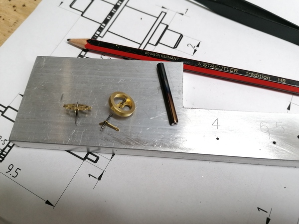
Cutting the pins to length went quite well. It is difficult to be precise, and inconvenient to keep putting in the pin vice and taking it out again, but it is much more precise than it was before.
Making the staking tool went very well. I gave it a nice polish with the grey scouring stuff, then hardened and tempered. I meant to temper the working face to a straw yellow but it looks like I over did it.
This is what it looked like straight after tempering:
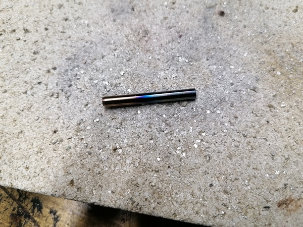
But evidently the colour continues changing. Need to be careful not to overdo it.
Using the staking tool and the precise-depth holes went pretty well. The only issue I had was that the shafts kept getting stuck in the holes, I think possibly because I only drilled the pivot holes to 0.5mm, where the shafts are out of concentric they get wedged in the holes.
I had to use Loctite on each one, but not really a surprise given how many times they've been fitted and removed.
< 2023-10-14 2023-10-16 >