Last modified: 2023-10-13 20:46:06
< 2023-10-12 2023-10-14 >Well I took a transformer out of an old laptop power supply and tried to connect the primary to the mains and the secondary to a voltmeter on AC mode, to work out what voltage I'm getting out of it, but it just kept blowing fuses. There is obviously more going on inside the laptop power supply that I haven't thought of.
But this is too much trouble so I'm going to stop for now, clear up a bit, and return to the watch. I've ordered a 240v-to-12v transformer from Amazon. Disappointing to have had to spend money though, when I obviously would be able to scavenge something if only I knew a bit more about what I was doing.
Next steps were:
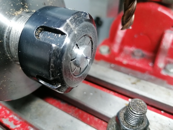
mk-gear for concentricity)So let's go and make a pallet fork shaft on the milling machine.
Well I think it makes squarer shoulders than the lathe does.
Although it still leaves a burr on the shoulder, and the pivot is not concentric with the shaft, and the pivot is slightly back-tapered.
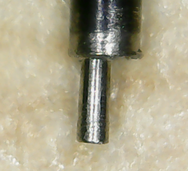
The eccentricity can be solved with something like mk-gear (but note this is cut with the tool on top instead of at the back, so we
need to lose the 90-degree offset).
I don't know what to do about the taper. Is this caused by the tram of the spindle, or is it because the rotary axis isn't level?
I think it is at least partly due to spindle tram, because on the other end I tried cutting at the same Z height but different X coordinate:
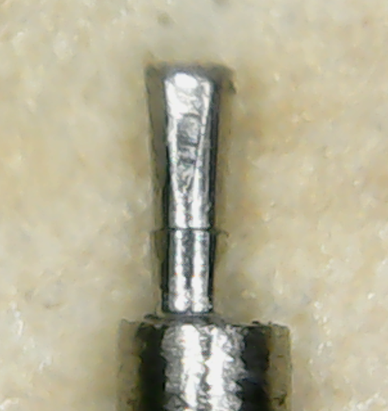
If it was just the rotary axis not parallel to X, then it would cut the taper at the same level regardless of the X coordinate of the tool.
So I will want to have another look at adjusting the spindle tram. And failing that, shimming up the front of the rotary axis is probably good enough, as long as I plunge in Z to cut the pivots, instead of leading in/out along X.
But first let's try and fit this shaft to the pallet fork.
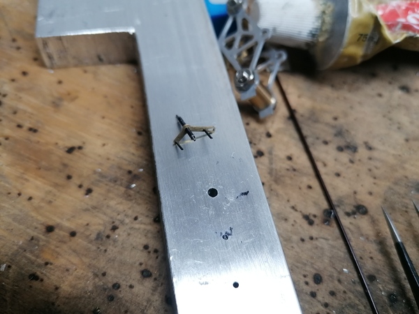
That was difficult, and I haven't done a very good job.
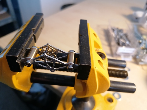
Nothing is square, or the right length.
I did however manage to get an acceptable press-fit this time, both on the shaft and on the pins. The tapered reamer idea is very good.
To fit the shaft I first used the 1mm tapered reamer to open up the hole, and then I put the shaft in the pin vice, positioned the pallet fork over a hole in the die block, and pushed the shaft into the hole by hand.
To fit the pallet pins I first used the 0.5mm tapered reamer to open up the holes, and then positioned the pallet fork over a flat solid piece of the die block, and tapped the pins in with the little hammer.
I used the 5x loupe while doing all of this. Even the miniature hammer is enormous.
So what have we got so far?
But flicking it back and forth by hand, it does seem to pretty much work as intended? Is this going to work? Seems unlikely.
Next up is to try to make a balance wheel with a hairspring.
I went and tightened up the gib screws on the Y axis and Z axis. The X axis ones seemed fine. Both Y and Z now have noticeably less play in them, so this should be a good improvement.
I observed about 0.6mm (!) of backlash on the Z axis, it seems to be caused by the leadscrew getting pulled up/down. May need to look at that.
I did try to cut another pivot to see if tightening the gibs had changed anything, but it still cuts a big taper, however I did work out why! It is because of the shape of the end mill. There is a slight taper on the bottoms of the teeth.
I took the top of the Z axis apart and tightened up the thrust nut on the ballscrew. I then measured backlash on all the axes with a dial indicator (advance forward to 0 on the indicator, advance forward by 0.4mm, advance backward by 0.4mm, read what the indicator says).
Results:
So tightening up the nut on Z was a big improvement, but the backlash on this machine is still awful. How does it compare to the router?
On the router the backlash is less than 0.01mm on every axis. It's actually too small for me to measure. It is indistinguishable from perfect, with my dial indicator. So the milling machine really wants to be better.
I took the plate off the Y axis belt drive area and found that the belt is slightly loose. This is responsible for 0.1mm of the backlash on the Y axis. Another issue is that the shaft of the motor is slipping slightly inside the pulley.
So I need to tighten up the pulley, and then tighten up the belt, and then re-measure the Y axis backlash...
That's brought the Y axis backlash down to 0.11mm, which is about the same as the other two. I can't see what the remaining problem is in the Y axis. Is the rest of it backlash in the ballscrews?? Is this why the guy sold it rather than finish building it?
How can I find out if the problem is in the ballscrews/ballnuts, or somewhere else?
Someone on reddit suggested greasing the leadscrew to take up the backlash. Doesn't seem like it would work but I'll try it.
Yeah, it didn't help, but I have set backlash compensation with BACKLASH = 0.1 on each joint, and that helped, although obviously is not
an ideal solution.
Cutting pivots with the 4th axis
So here's the plan for cutting pivots with the 4th axis.
First we'll measure the runout with a dial indicator, as in mk-gear. And then we'll run like a helical toolpath
that meshmill generates, that advances the cutter maybe 0.1mm/rev or something, but with the Z axis moving to
counteract the runout.
It will start "off" the end of the pivot, then move in at radius 0, step up to like 0.2mm radius, chamfer across diagonally to 0.25mm radius, cut a straight pivot at 0.25mm radius, then step straight up to 0.4mm, then chamfer across to something exceeding 0.5mm radius, to make a nice chamfer to the rest of the shaft, without leaving a burr.
What could go wrong? Well, the 0.6mm backlash in the Z axis will prevent the runout compensation from working. So, back to milling machine adjustment, let's look at what is wrong with the Z axis.
I wrote the program to calculate the helical toolpaths: https://github.com/jes/concentric-gear-cutting/blob/master/mk-pivot - not tested yet.
Still have to wash motorbike, lube chain, replace that bolt. Also change the oil in the car.
Try out the mk-pivot program.
Then make a balance wheel, collet, hairspring, shaft, put it in the frame, and try to make it tick by hand.
< 2023-10-12 2023-10-14 >