Last modified: 2023-10-07 20:32:05
< 2023-10-04 2023-10-06 >I want to make the parts in an order that will allow me to check the interaction of the escape wheel and pallet fork as quickly as possible. So I need:
And then I can try to turn it by hand, and work out whether/how to proceed.
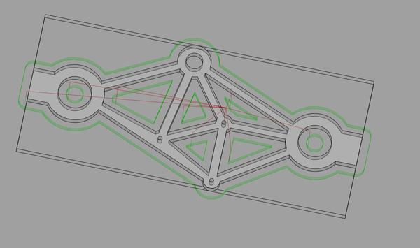
I'm going to do straightforward CAM, with no separate finishing passes, and see how it looks. If it is bad I can do better, but should be fine as none of the outside edges are really functional.
The drill holes are at:
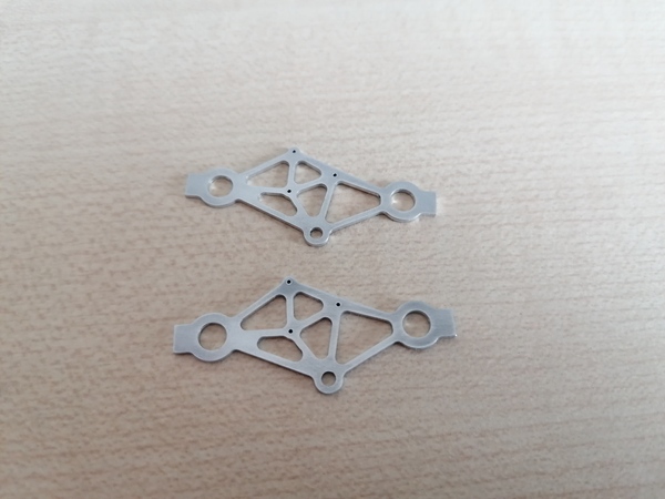
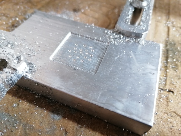
Great success.
The 4 holes in the middle were drilled to 0.5mm with the PCB drill, and then the rest was machined with the 2mm endmill.
I used a piece of 0.5mm blue pivot steel to check the hole diameters. It did not fit at first, so I dragged the end of it over a file to give it some rudimentary "cutting edges", then used the pivot steel in the pin vice to work the pivots until they were large enough for the pivot steel to spin freely. This technique worked very well.
I drilled the large hole out to 2mm with twist drills in the pin vice, and then opened it up with a piece of "sharpened" 2mm pivot steel, as for the 0.5mm holes.
I wet-sanded the faces with the sandpaper on the piece of plywood, mainly to deburr the edges, then wet-sanded with 1000 grit sandpaper held in the hand, and then polished with Autosol.
There are some machining marks visible around the edges (which I haven't polished). This may have been improved if I ran a separate finishing pass.
The Z depth was set a bit wrong on the second part, which meant the first pass was quite deep, but it seemed to work well and made a nice chip, so I have increased the suggested depth of cut in micromachining.md from 0.32mm to 0.5mm.
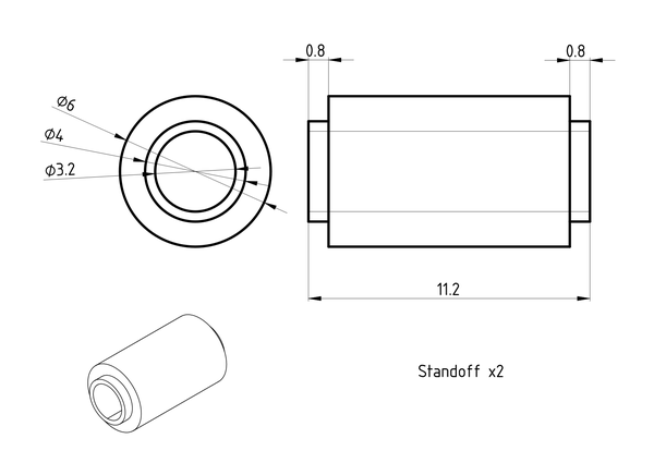
After lunch: onto the standoffs!
Drawing:
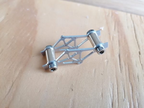
Parts:
The length of the central section is specified at 9.9mm but I made it at 10.0 mm (by accident). The only effect this will have is to give 0.1mm more end-float on the shafts, which I don't care about.
There is more slop in the standoff mountings than intended, which means careful assembly will be very important to make sure the shafts aren't binding.
It still doesn't work!
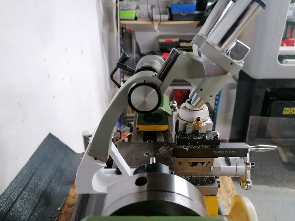
The focal point is still at the limit of travel, and even at the limit of the slots it can't point at the centre line of the lathe. With the tip of the tool in the centre of the frame it is 10mm away from centre line.
I kind of feel like I failed to save the FreeCAD file after I made some changes last time, not sure.
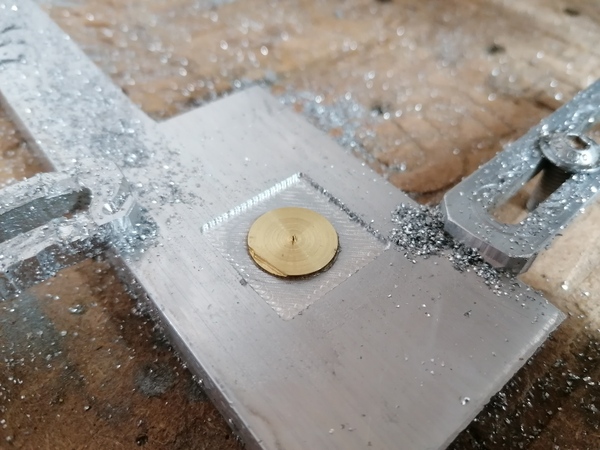
I've parted off a disc of brass, it's 1.14mm thick. I'm going to surface off a piece of aluminium on the CNC router, glue the disc down, then surface off the brass 0.5mm higher than the aluminium, so then the disc will be 0.5mm thick. Then use a PCB drill to put a (tight!) 1mm hole in the centre, and then do some CAM for the actual escape wheel.
On the first attempt, surfacing the brass flicked the glue loose.
Next try:
OK, that worked.
Next up: initial machining of the shape, with the 2mm end mill.
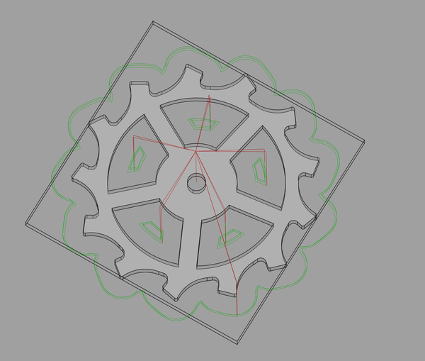
This time I am running a "roughing" pass with 0.1mm material left behind, followed by a finishing pass, will see if it makes much of an improvement to surface finish compared to the frame plates.
It lifted it off the superglue again, frustrating: https://www.youtube.com/watch?v=4jOMCA3yU3k
So ideas include: