Last modified: 2023-10-04 20:20:14
< 2023-10-02 2023-10-05 >I said:
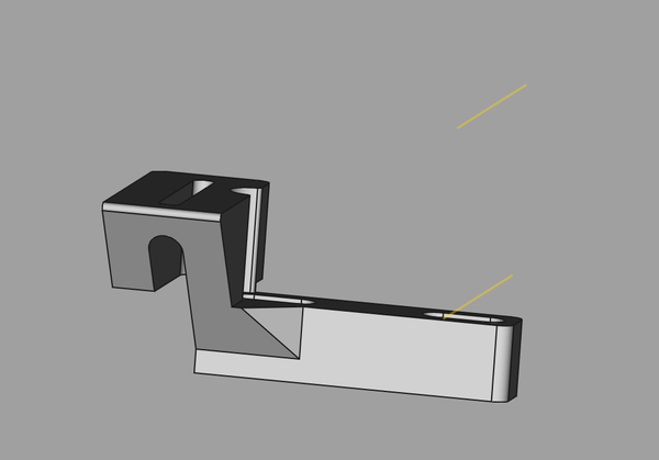
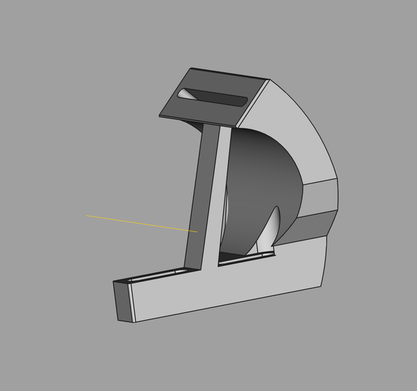
the carriage microscope is slightly too close to the work, the position where it's in focus is just beyond the end of its travel. Also it doesn't have enough travel left/right or forward/back, so I should make a new mount for it that rectifies these problems. Also the mount is a bit floppy, and it would be better if the eyepieces ended up at 45 degrees instead of vertical.
So it needs:
The 45-degree tilt is the hardest part, because I don't know where the actual focal axis is.
What I can do is drive it to the end of its travel, position something at the focal point, and then measure this position relative to some reference on the bracket, then I can put a datum line there in CAD, and then I know I need to rotate the mounting surface around that line.
It's about 45.5 mm above the surface of the bracket that clamps down to the carriage, and about 7.5 mm back from the front of it.
Oh, that's when it's at the end of travel. I should measure the length of travel and position a second datum line at the bottom. The travel is about 40mm.
So actually I think it will work if the flat bit that the microscope bolts to is level with the rotation axis. So that should be easy enough.
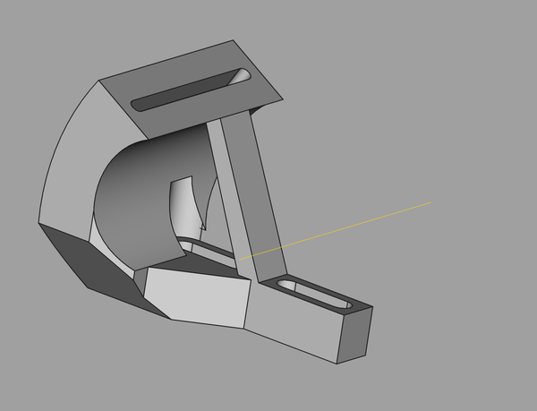
Sighting across that surface, I can see the datum line:
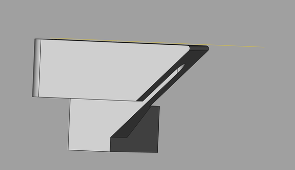
Now want to tilt the surface, but maintain that property.
Well, it's not exactly pretty...
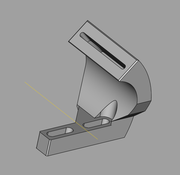
But maybe it'll do the job?
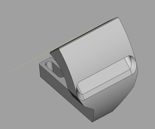
Actually, I'll just add a bit more rigidity...
Lovely job. Let's print it in PC Blend and see how we go. Actually just PLA for now. If I like it but want it stronger, then PC Blend. Maybe rather than PC Blend I should instead find a way to integrate some metal rods to make it stiffer. I think stiffness will be more important than strength.
Well this was a fail:
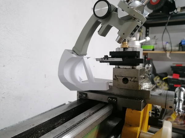
45 degrees doesn't work because it hits the tool. Maybe try 30 degrees or 22.5 degrees.
Also the bolts aren't long enough, need to make the counterbore deeper, or whatever.
OK, update:
Must print this out tomorrow.
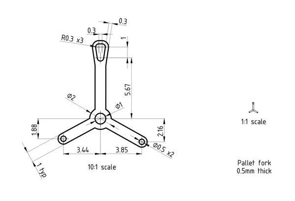
Let's go with 1x scale, but module 0.4 on the gears, and 0.5mm for the small pivots.
Scale drawing of the pallet fork:
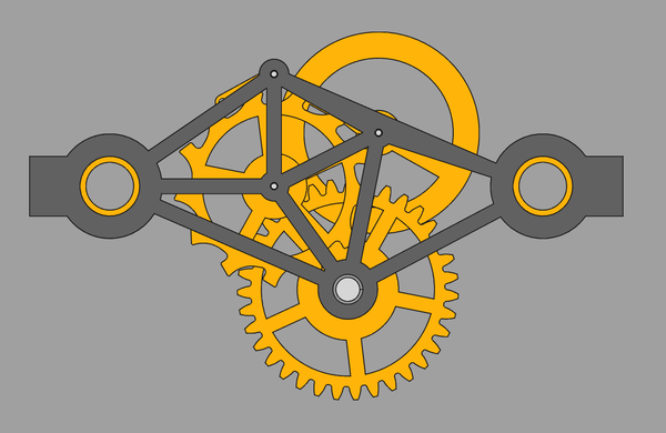
And a layout of the whole mechanism:
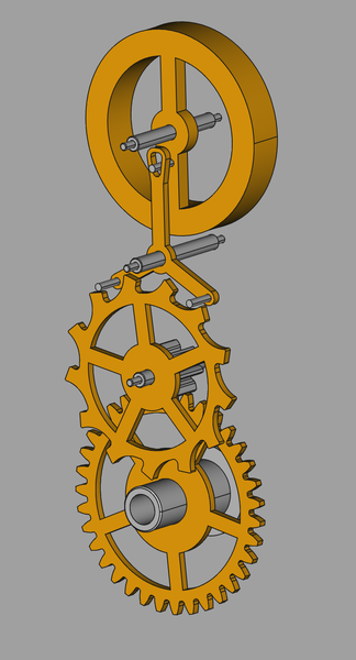
This is mostly the same as the model on the desk, except with a 7-tooth pinion instead of 8-tooth, and corresponding reduction on the barrel gear from 40 teeth to 35 teeth.
The barrel gear has a 2mm bore, for a 2mm rod to go through, with the idea that the 2mm rod can be removed to wind the string.
I didn't make the pallet fork in the "English lever" shape, but I will want to move to that eventually because it allows the escape wheel and balance wheel to get closer together.
I will probably also want to experiment with making the lever longer, because that allows for a larger balance wheel.
Oh, this also lacks provision for a hairspring, and it could be thinner if the escape wheel were moved to the other side of its pinion.
Hmm, if I bend the lever too far, then the escape wheel can't go the other side of its pinion else it will interefere with the balance wheel. So the question is do I want to make it as thin as possible, in which case I move the escape wheel past its pinion and limit how far around I bend the lever so that they don't interfere, or do I want to make it with the lowest overall diameter, in which case I leave the escape wheel where it is and bend the lever as far as I possibly can?
I think let's go for smallest overall diameter.
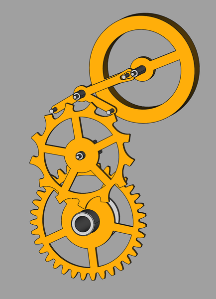
Here it is with the lever bent by 20 degrees:
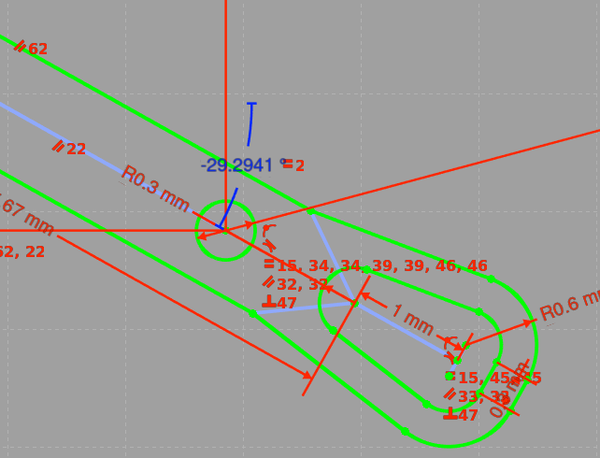
I'd like to try putting the "lever" arm inline with the discharging pallet arm, just seems elegant that way. Let's have a look at that. It's at 29.2941 degrees from horizontal (blue dimension):
Hmmm, it definitely could work, but in the configuration I have here it interferes with the escape wheel pinion:
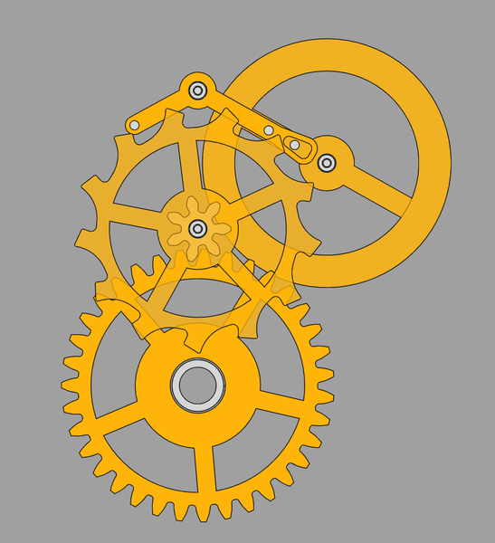
But I do like the simplicity of only having 2 arms on the "pallet fork", and it is much more compact than the first layout above, despite being totally equivalent. So maybe I just need to make that pinion a bit shorter.
Here's a folded-up layout, with a "skeletonised" frame:
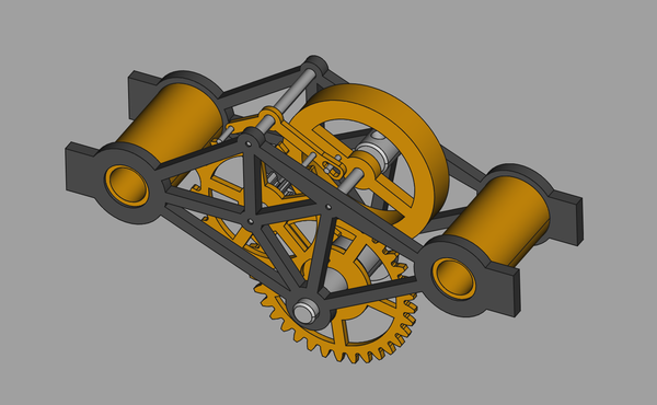
The tabs on the sides of the frame are to help hold it in the vice. This is designed to have M3 bolts running through it, but at some point we could switch to using M1.6, or smaller, threaded into the standoff at each end?
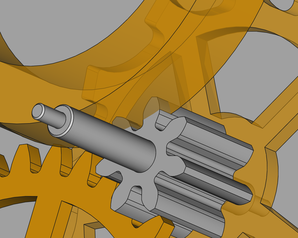
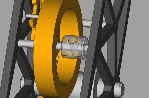
Includes a "collet" as described in 2023-09-21:
I don't know how the hairspring is going to be attached to the frame. Will improvise that when I get to it. Maybe cable tie it to the standoff??
This is in metal-escapement2.FCStd.
Materials required:
The width at the root of the escape wheel pinion is only just under 0.5mm - possibly could make this with the tapered ball-end mill instead of making a special gear cutter?
The slot in the lever has 0.3mm radii - maybe I could clear out most of this with a 0.5mm PCB drill and then try to use those burr-like fibreglass end mills to finish it up?
Firstly look in CAD to get the locations of holes, which are 0.5mm, 2mm, 4mm diameter. Drill them all through with maybe a 0.5mm PCB drill (the rest to be opened up by hand later).
Then use either the 2mm tool or 1mm tool to cut out the shapes.
Print out a techdraw drawing, make on the lathe.
First drill the hole for the shaft (1mm). Remember it must be a tight fit.
Cut most of the shape with 2mm end mill. Then re-cut the profiles with 1mm end mill. Then try to use a 0.5mm fibreglass-cutting weird tool to get the roots of the teeth. Failing that, make a custom cutter and do a "gear-cutting" type operation using the milling machine.
May need a custom silver steel gear cutter for the pinion leaves. Module 0.4, 7 teeth. Before making a custom cutter, try cutting it with Meshmill in "horizontal" direction in rotary mode, with the tapered ball-nose end mill.
Cut the shaft on the lathe with a blank area for the pinion, then move to the milling machine to cut the pinion. May need some creative workholding to stop it deflecting, ideas include:
Remember shaft must be a tight fit in escape wheel and run freely in the frame plates.
Remember the (large) bore must be a tight fit on the barrel.
Print out a techdraw drawing, make on the lathe.
Remember it must be a tight fit on the bore of the barrel gear.
Cut way over-length to allow for insertion/removal.
First drill the hole for the shaft (1mm) & impulse pin (0.5mm). Remember they must be a tight fit.
For cutting, can probably get away with the 2mm tool. May wish to tidy up with 1mm tool.
The material is already mostly the right size, just needs the pivots turning in the ends. The shaft must be a tight fit in the balance wheel/pallet fork, and the pivot must run freely in the frame plates.
If blue pivot steel is too hard to cut, maybe revert to unhardened silver steel, and come up with a method of hardening. Or maybe temper the blue pivot steel and try again.
Print out a techdraw drawing.
Cut a short length of aluminium rod, cross-drill it on centre line to maybe 1.2mm (can be expanded later if necessary) using the PCB drill in the milling machine, then transfer to collet chuck and drill and turn to final dimensions.
Need to improvise a hairspring. Likely candidates are the scrap watch mainspring, or bend up some 0.7mm stainless wire, or buy some music wire thinner than that. Also need to improvise a way to attach it to the frame.
First drill the holes for the shaft (1mm) and the pallet pins (0.5mm). Using the 0.5mm drill, also drill at the top and bottom of the pin slot.
Now try to use the weirdo fibreglass-cutting endmill to cut out the slot, and then cut out the outline using 2mm or 1mm endmill.
Cut to 2.5mm length. Must be tight fit in pallet fork.
Cut to 3mm length. Must be tight fit in balance wheel.