
As part of my YX140 scooter project (now finished) I discovered that the scooter's speedometer is controlled digitally. There was a sensor in the original engine which generated pulses to signal the speed of rotation of the gearbox output shaft. The new engine has no such sensor, so I had to do a little electronics to make the speedo work.
The old speedo sensor has 3 wires leading to it. One is tied to ground, one is +7v, and one is the output signal. I watched this YouTube video to find out how the sensor works. In short, it pulls the signal wire to ground every time the sensor registers the passage of a tooth on the gear it is sensing, and leaves the wire floating when no tooth is passing.
So all I need to do is measure the speed of the scooter in some way, and then pull the signal wire to ground at some frequency to make the speedo register the correct speed.
To measure the speed, I opted to place a magnet on the front wheel, with a hall effect sensor to detect the passage of the magnet. This is a much lower-frequency signal than the one given by the gearbox sensor, but at speeds above walking pace it's good enough to work perfectly well.
To give the corresponding signal on the speedo signal wire, I wrote a short Arduino program that uses the ATmega's "Timer1" to generate a PWM signal that then controls a transistor to connect and disconnect the signal wire to/from ground. I wanted to use an ATtiny but I couldn't work out how to drive any of the ATtiny's timers at a high enough precision to cover the full range of speeds that I'd need to display. It's probably possible, it's just easier to use an ATmega.
Here's the rather messy circuit I made on a piece of perfboard:
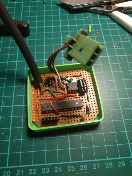
The green connector plugs into the existing speedo sensor connector on the scooter, and the black cable leads to a connector for the hall effect sensor I need to place on the front wheel.
The circuit is just a 5V voltage regulator, a filtering capacitor (probably unnecessary, but can't hurt), an ATmega328 microcontroller (running Arduino etc. as described here), a transistor for the output signal, an LED for debugging, and a convenient programming header Just In Case™ I didn't get the software right first time. The board looks more complicated than it is because I'm bad at layout.
It's in a 3d-printed case, and I filled the case with black polyurethane resin to keep everything nice and secure against vibration and water ingress:
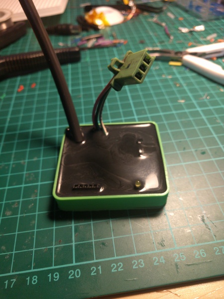
Looking good, don't you think? What I hadn't considered is that the programming header is not watertight, and I inadvertently filled it up with resin! Let's hope I never have to reprogram the ATmega...
I 3d printed some parts to hold the magnet and the hall effect sensor, and attached them to the front wheel:
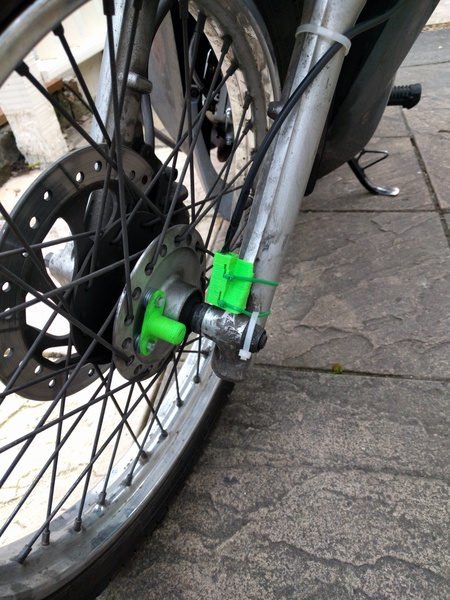
(At some point I'd like to replace the magnet holder with one that doesn't need to be spaced away from the hub with washers, and I'd like to replace the hall effect sensor holder with something that can stay in place with fewer cable ties. But these work OK for now.)
The LED on the circuit board lights every time the sensor detects the magnet. This makes it easy to position the sensor and the magnet without having to spin the wheel fast enough to register a speed on the display.
Having aligned the sensor and the magnet, I set off for a test ride and was disappointed to find that the sensor only intermittently detected the magnet, causing the speedo display to wave around erratically. My initial attempt at the software tried to "auto-range" the analogue signal from the sensor, but that turned out to be unreliable when the magnet was moving too fast. That meant I had to modify the program, and that meant I had to use the programming header. The one that I'd filled with resin.
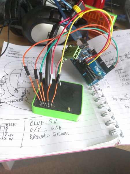
I spent an hour or so scraping away little bits of plastic until I managed to expose some small pieces of conductor in the programming header. I then soldered some short orange wires on to the conductors and was able to successfully upload an updated program to the ATmega! I simply replaced the elaborate auto-ranging code with a fixed threshold, and that worked much better. The speedo now works nice and smoothly, and apart from the rather attractive green mass attached to the front wheel, you'd never know it wasn't working the way Honda intended.
I debated removing the orange wires from the programming pins, but in the end I just wrapped them in insulating tape and left them on. They might be useful one day.