
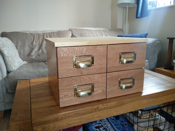
For the last ~3 weeks I've been working on a chest of drawers. This is no ordinary chest of drawers, they are puzzle drawers. The idea is that the puzzler is presented with one of the drawers already open, and the goal is to manipulate the chest into a configuration where all of the drawers are closed. With a typical chest of drawers, this would be easy: just close the drawer that is open. In the puzzle drawers, there are 3d-printed internal mechanisms linking the drawers together.
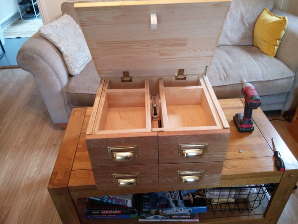
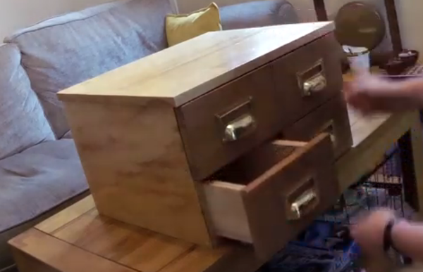
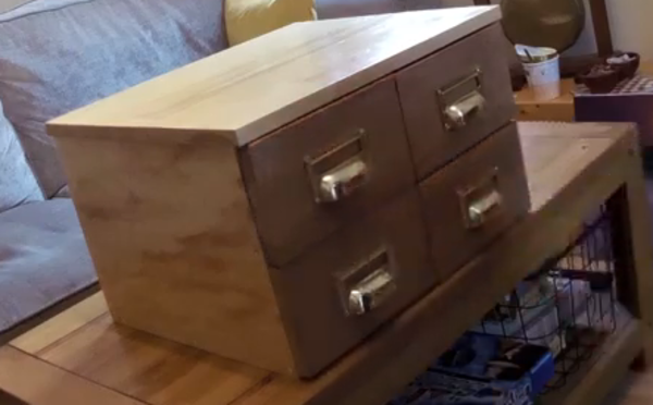
Here's a picture of the finished drawers:
Assembly
We start with an open chest:
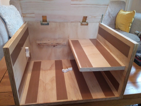
The chest is made from plywood, and is glued and screwed together.
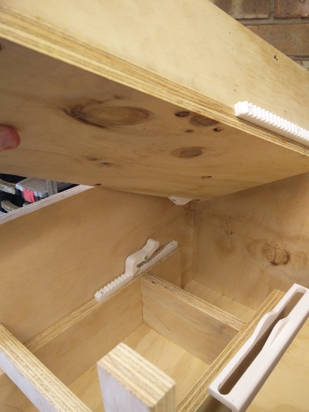
There are two spring-loaded 3d-printed ratcheting teeth mounted inside the box. These will engage against sawtooth racks on the drawers. You'll also notice some suspicious brown tape, this is teflon tape and is there to provide low-friction surfaces for the drawers to slide on. It works well, the drawers slide much more smoothly on the teflon tape than they do directly against the wood.
The right-hand upper shelf is permanently fixed in place, but the left-hand upper shelf comes later.
Next we install the lower right-hand drawer:
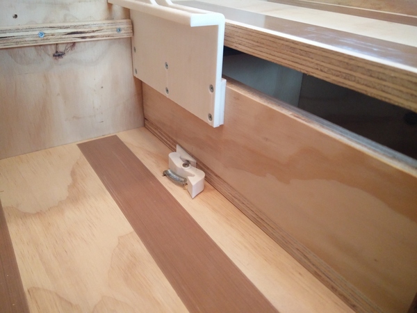
When the drawer is in the fully-closed position, the plastic bump on the edge of the drawer lifts the adjacent ratchet tooth. This will come in useful later. There is also a large plastic plate that rises to the upper level. This will also come in useful later.
Next we have to install the lower-left drawer and the cross-shaped front assembly of the chest. I originally tried to make a video of myself assembling the cabinet but it didn't go very well. Here's a still of me trying to get the lower-left drawer into place:
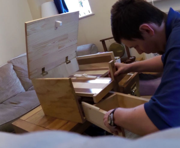
The cross piece is made of two pieces of plywood with a lap joint.
Each of the drawers has a wooden part mounted on the side that knocks against the cross-shaped piece to stop the drawers from falling out. This means the drawers need to be in place before the cross-shaped piece can go in. But the drawer fronts also mean that the cross-shaped piece can't slide in after the drawers are already there, and the large plastic plate on the lower-right drawer means that the shelf on the back of the cross-shaped piece can't be dropped in from above. Figuring out how to make this so that it can actually be assembled was a puzzle all of its own!
The cross-shaped assembly is retained with screws, but not glue, so that it can be removed later for maintenance.
With the lower drawers and the cross-shaped piece installed, we come to the upper level:
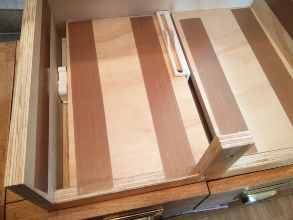
The left-hand ratchet tooth is now engaged with its sawtooth rack, and the large plate from the right-hand lower drawer is aligned with the hole in the left-hand shelf.
We can drop in the right-hand upper drawer and fit the gear:
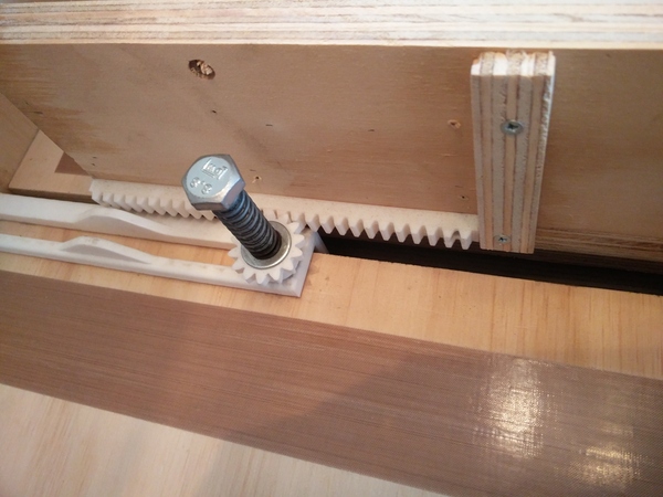
The spring-loaded gear is installed with the aid of an M10 bolt that threads directly into the plywood shelf. I wouldn't necessarily trust a wooden thread like this to hold much load, but it only needs to hold the gear in place and seems sturdy enough. This photo also gives a good view of the plywood piece that stops the drawer from coming out too far. We also see the other key mechanism inside the chest: when the lower-right drawer is pulled out about halfway, the lumpy part on the large plastic plate raises the gear up so that it no longer engages with the toothed racks of the upper drawers.
The plastic gear turns directly on the smooth shaft of the bolt. I put a few drops of 3-in-1 on it, but if wear becomes a problem it could be sleeved with a piece of steel or similar.
Now we can drop in the left-hand upper drawer:
When both drawers are closed, and the gear is engaged, neither drawer can be opened. When the gear is disengaged, the drawers can move independently (for example, one drawer can be pulled out). When the gear is re-engaged with one drawer opened, closing that drawer pushes the other drawer out.
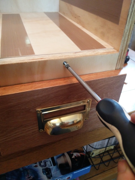
The left-hand upper drawer has a plastic lump on it similar to the one on the right-hand lower drawer, to disengage the left-hand ratchet tooth:
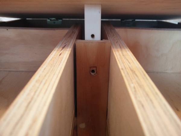
We now come to closing the lid. The lid is made of a board of laminated pine planks. I bought this ready-made from B&Q and just cut it down to size. The lid has a plastic part with a hole in it, which lines up with a hole in the front assembly:
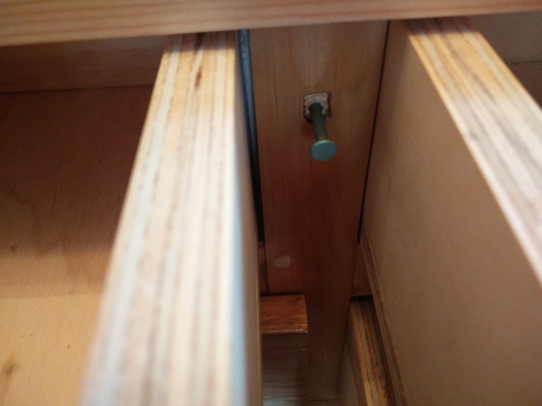
A bluntened nail is inserted through these holes to keep the lid closed:
And then the drawers can be closed, and the chest is complete:
To reopen the lid, the top two drawers need to be opened, and then the nail needs to be pulled out, either by prying on it with a screwdriver, or (my preferred method) pulling it out with a magnet.
The chest weighs 18kg in total. It can be lifted by the lid, but since the lid is only held down by a small 3d-printed piece, I prefer to lift it from the bottom.
Puzzle & Solution
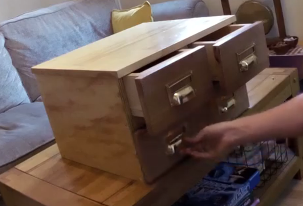
Now that we know how the chest is assembled, we can think about solving it. I recorded a video of myself solving the drawers, so you can watch it if you want to see it in action, but there is no explanation in the video:
The initial configuration has the lower-left drawer pulled out:
The right-hand ratchet is disengaged at this point, because the lower-right drawer is closed, but the left-hand ratchet is preventing the lower-left drawer from closing. So we need to get the left-hand ratchet disengaged.
The left-hand ratchet disengages when the top-left drawer is pulled out about 1/4 of the way, but the top drawers won't move because they're geared together and both closed. So we need to disengage the top gear.
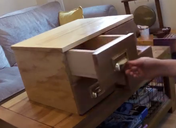
We pull the lower-right drawer out until it meets resistance against the spring-loaded gear. This disengages the gear so that the top drawers can be moved:
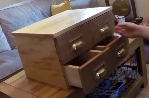
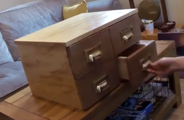
We now need to open one of the top drawers:
With the top drawers now separated, we can close the lower-right drawer again. Remember the lower-right drawer needs to be closed in order to disengage the right-hand ratchet on the lower-left drawer.
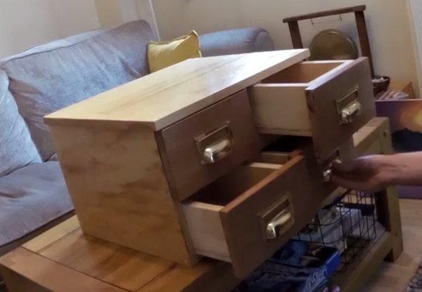
Now we need to position the top-left drawer about 1/4 of the way out so that the left-hand ratchet is disengaged. This will also result in some movement of the top-right drawer but we don't mind at this point.
At this point both of the ratchets are disengaged, and the lower-left drawer can be closed.
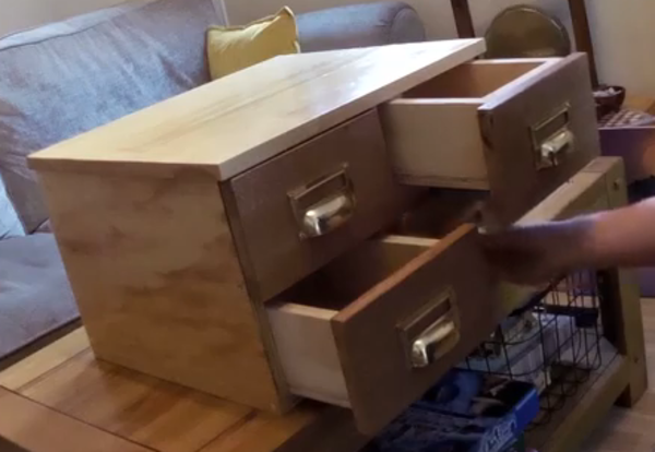
But we still have the top two drawers geared together, so it is impossible to close more than one at any time. To solve this, we again need to pull out the lower-right drawer until it disengages the top gear.
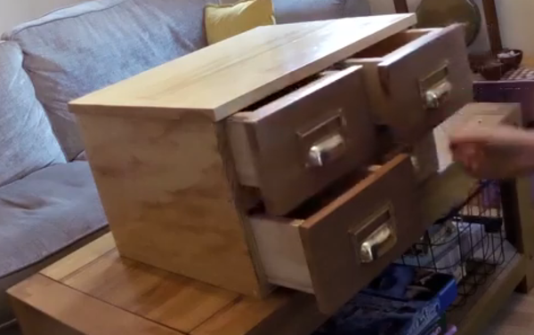
Then we can close both of the top drawers:
Finally, we close the bottom-right drawer and the puzzle is solved.
More
Several people suggested that puzzle drawers could be a good addition to an escape room. I think this might work well if the design were modified so that the goal is to open a particular drawer rather than to close it, so that a key or a clue could be hidden inside that drawer. Probably this would be as simple as reversing the ratchets on the lower-left drawer. Come to think of it, I wish I'd done that in the first place.
One thing I really hate about certain types of drawers is when they don't open far enough to be able to see the things at the back of the drawer. Unfortunately the puzzle drawers have hardware mounted on the sides which we don't want the puzzler to be able to see, so the movement of the drawer must be constrained to only 50% of the length of the drawer (and, in practice, slightly less). This is a problem. For this reason I have mounted the "backs" of the drawers about 3/4 of the way along, instead of all the way at the back. This has the effect of shortening the drawer so that things inside can't roll back as far. I've not yet reached a conclusion as to whether I prefer a deep cabinet with deep drawers which I can't see the back of, or a deep cabinet with short drawers.
A week ago I posted a video showing the mechanisms working for the first time, and at that point the top gear didn't engage very reliably. At 00:25 in the video you can hear a "click". I had anticipated this problem, and beveled the bottom edge of the gear to try to avoid it, but what I hadn't realised is that beveling the bottom edge of the gear doesn't actually make it any easier to engage at all.
Old gear on the left, redesign on the right:
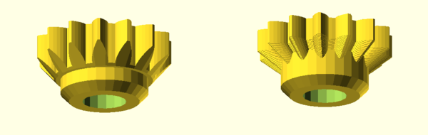
The width of the teeth at any given radius from the centre is still exactly the same as it would be if there were no bevel (left). I solved this (right) by tapering the size of the teeth towards the bottom, instead of just chopping them off at a taper. The gear design library that I use in OpenSCAD doesn't support this, so I created the tapered gear by stacking a large number of very thin gears, of different sizes, on top of each other at 0.2mm increments. Since I 3d print at a 0.2mm layer height, this is functionally equivalent to a smooth taper.