
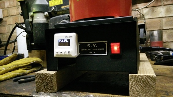
For my 3d metal printing project, I need the sintering furnace to stick to a pre-defined temperature profile. Unfortunately, the controller that my furnace came with only allows you to set a constant temperature. It maintains a constant temperature very well, but the operator frequently has to manually update the temperature in order to stick to the defined profile.
TL;DR is I ended up making an Arduino-based industrial process controller with custom PCBs and a 3d-printed case:
CAL 9500
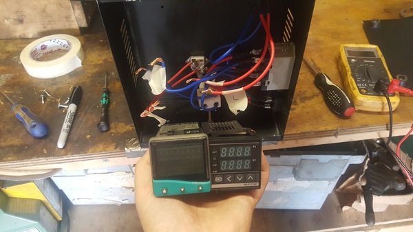
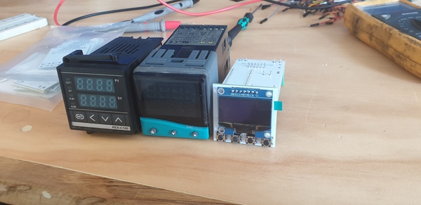
I first bought a secondhand CAL 9500 (left) to replace the REX-C100 (right) that the furnace came with.
This is a process controller, which means that in addition to setting a constant temperature, it allows you to program in a profile for how you want the temperature to change over time. I wired the CAL 9500 into my furnace, and I was just starting to figure out how the menu system works and how to program it.
I noticed that the device was getting quite warm but didn't think too much of it. Eventually it fizzed and then banged and then the magic smoke came out and it didn't work any more. I think I was sold a pup.
But from what I saw of the CAL 9500, I didn't like it. The way the wires are attached to the back, combined with the poor access inside the chassis of the furnace, means it is impossible to fit the controller in the front panel if the wires are already attached, but it is also impossible to attach the wires if the controller is already in place. To solve this I hacked a slot out of the bottom of the front panel so that I could connect the wires and then slide the controller in (hence the gaffa tape in the photo above), but I now wish I hadn't. I also found the small buttons were hard to press and hurt the ends of my fingers, which is doubly problematic as the interface in many places requires you to hold down 2 buttons for several seconds at a time. And finally, it is impossible to find anything in the interface without consulting the manual, and even then it is hard to understand.
Arduino
A new CAL 9500 is over £200, which I'm not interested in spending. The seller of the secondhand one said they'd send me another, but they still haven't. So my next idea was to build my own process controller using an Arduino Nano. I used 4 buttons instead of 3 so that "chording" wouldn't be necessary, and I used an OLED screen instead of 7-segment displays so that the screen can display enough text to make the interface understandable. Then I used a MAX31855 breakout board to interpret the signal from the thermocouple, and a solid-state relay to switch the furnace relay on and off.
The OLED screen is an SH1106, which is almost the same, but not quite the same, as the much-more-common SSD1306. The protocol is different enough that you need to go out of your way to find a library that supports it, but similar enough that the library is still just called "ssd1306". If you try to drive an SH1106 as if it's an SSD1306 then only the top 8 rows of pixels work, leading you to believe that the screen is broken. That took me a while to figure out. The screen is driven over SPI.
The MAX31855 is also driven over SPI, and the solid-state relay just needs 1 pin to switch it on/off.
The Arduino program ended up surprisingly complicated, and most of it is just spaghetti code to implement the menu system. The code is on github. I ended up limiting the maximum number of program segments to only 16, because the Arduino only has 2KB of RAM, and I was using too much. It would be possible to cut the memory usage down by, for example, removing the unused fonts from the ssd1306 library, and allocating fewer static arrays for each program segment, but I think 16 will do me for now.
But it's 2019, and even the Arduino Nano isn't that small. I shouldn't have to worry about fitting my program inside 2KB! It seems like there should be something in the same form factor as the Arduino Nano, but with substantially more memory and CPU power. Probably there is.
Each program segment has a type, a target temperature, and a duration. The type is either "step" or "ramp". A "step" segment sets the temperature setpoint to its target temperature immediately, and then holds it there for the duration of the segment. A "ramp" segment ramps the setpoint linearly from wherever it was at the start of the segment to the target temperature, over the course of its duration. You build up a temperature profile by chaining together these "step" and "ramp" segments.
Breadboard
Here is the first working version, wired up on a breadboard:
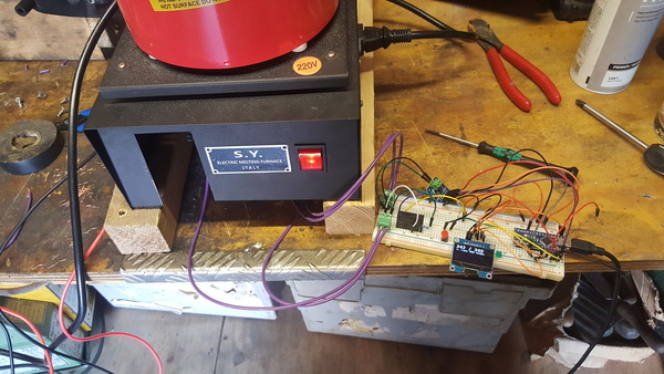
(I didn't have enough buttons on hand at this point, so the red button is the "OK" button, and all other inputs are conveyed by connecting/disconnecting jumper wires).
If you zoom in, you may notice a spurious resistor next to the solid-state relay. The Omron G3MB-202P solid-state relay has "zero-crossing" behaviour, which means that, when you ask it to switch off, it only actually switches off when the load voltage crosses 0 volts. The idea here is to reduce back-EMF or something when switching AC loads, not entirely sure. But the problem is that the relay inside the furnace that actually switches the coil on and off also seems to have some electronic control, which means the "load" applied to my solid-state relay draws almost no current at all. That means the solid-state relay can't actually tell when the load voltage has crossed 0 volts, so it just switches the load on and never switches it off. Disaster! Adding a 10 kOhm resistor in series with the load makes it draw enough current so that the solid-state relay switches off when you want it to. Or, at least, that's my best guess at what is going on.
PCBs
Normally at this point I would build the project up on prototyping board and then call it done, but this time I wanted to be a bit more professional, so I designed some PCBs using KiCad. The user interface is quite hard to understand at first, I recommend the Getting To Blinky playlist on the Contextual Electronics YouTube channel, although note that some of the key bindings seem to have changed between KiCad 4 and 5, so you'll have to figure that out on your own.
To make the project fit neatly in the "1/16 DIN" panel mount available on the furnace, I decided to split it across two PCBs. One PCB would be mounted vertically and contain the OLED Screen and 4 buttons, and the other PCB would mount horizontally, inside the chassis, and contain the power supply, Arduino, and solid-state relay.
To make each PCB, you first draw the schematic in the "Eeschema" part of KiCad:
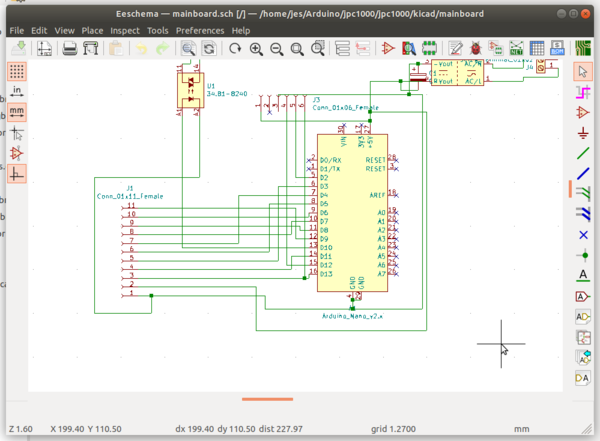
and then you draw the actual PCB layout using "Pcbnew", while KiCad automatically makes sure that you don't connect things that shouldn't be connected, and you do connect things that should be connected:
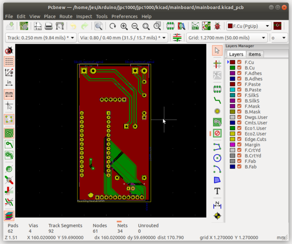
Laying out the PCB is a surprisingly fun task, it's almost like a puzzle game.
This is a 2-sided PCB, and the holes for the component legs are "plated through holes" which means the component legs are electrically connected to the copper on both sides of the board. This is useful as it means you can run traces between components on either side of the board, which means traces can "overlap" each other without you having to solder in wires to jump them over one another. Another cool feature of 2-sided PCBs is "vias". A "via" is just a plated through hole that you don't solder any component leg to! This creates a connection through the middle of the PCB that connects the top side to the bottom side, such that you can route a trace somewhere on the board, then drop it down to the other side through a via, and then continue routing on the other side. This makes routing the final few traces much easier, when the board is already populated with other traces that are getting in the way.
Having laid out the PCB, you need to generate "Gerber" and "drill" files in order to get it manufactured. The drill files obviously just describe where (and in what size) holes need to be drilled on the board. The Gerber files are instructions for a plotter that describe what is on the different layers of the board. There is more than just "copper or not copper", there is also a "solder mask" layer for each side, which is the stuff that actually gives PCBs their colour: solder mask is a layer applied above everywhere that you don't want to solder, to prevent solder from spreading along the traces and covering the entire board. It also prevents metal items that touch the circuit board from shorting out the traces. There is also a "silk screen" layer for each side, which lets you put writing and graphics on top of the solder mask, although I understand that if you are only having a small number of boards made, the manufacturers tend to apply this with an inkjet printer rather than make an actual silk screen.
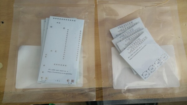
There are many companies that will take Gerber and drill files and manufacture you a PCB, extremely cheaply. I used JLCPCB, because they sponsored some of the electronics YouTube videos that I watched. You can watch a tour of the JLCPCB factory on YouTube, it is very interesting. In total I was charged about £15, for which I got 5 copies (the minimum order quantity) of each of my 2 PCB designs, delivered to my door, from China, in under a week. What a world we live in.
While soldering the components on to the boards I realised that I had 2 of the pads swapped for the solid-state relay, which means the Arduino wouldn't be able to switch it on and off. That's annoying. I also had forgotten to include the resistor that makes the solid-state relay able to switch the load. I solved both of these problems by connecting the solid-state relay to the PCB with "bodge wires", although unfortunately I don't have any photographs of this and it's now tucked away inside the furnace chassis so you'll just have to imagine.
With the boards soldered up (modulo the solid-state relay, because I was still working out what to do about it at this point), they can be plugged together via an 11-pin right-angle header:
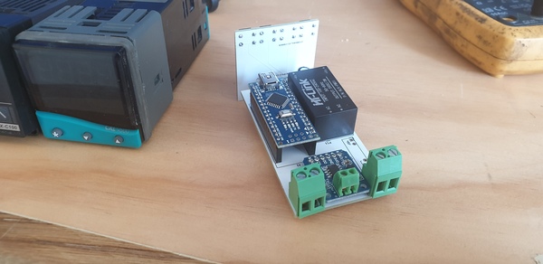
The big black box is the power supply. There are 2 screw terminals for the AC power, 2 that get connected/disconnected by the solid-state relay, and 2 (small) for the thermocouple.
So far I have done 2 sinters with this device. On the first one I had some trouble with the power supply, as I was still running it on the breadboard and powering it off a laptop, but the second one used the power supply on the PCB and worked flawlessly for the whole 12 hours.
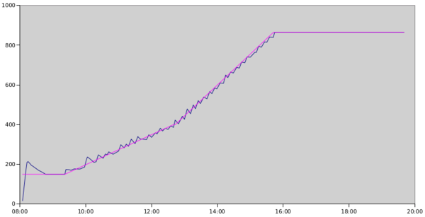
The improvement of the process controller over manual control is not only that I no longer have to waste loads of time updating the temperature setpoint, but also the setpoint is tracked much more accurately. Here is the temperature profile that I managed when updating it manually, compared to what the process controller managed:
vs
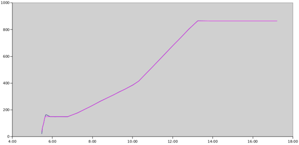
(Again, sorry, no axis labels. Gnumeric makes this hard. X is time, Y is temperature in °C, pink line is desired temperature, blue line is measured temperature).
The process controller got almost every datapoint within 1°C of the target. The only time it didn't do this was the initial overshoot after the step up to 150°C at the very start, which notably is also improved compared to when the furnace was controlled by the REX-C100.
Plastic case
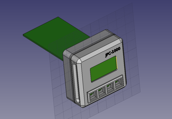
Obviously the only thing left to do is a 3d-printed plastic case.
It's likely that I'll want to reprogram the Arduino at some point, so I need the front panel PCB to be removable in order to gain access to the USB port. To this end, I made the plastic case in 2 parts: one part holds the main board to the panel on the furnace, and the other part is a neat cover for the front panel PCB.
The main board is held in a piece of plastic by some slots and a single screw, and then the plastic piece is held in the furnace by a thin plastic piece that screws on to it, with the metal panel sandwiched between the two:
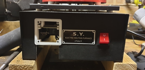
The front panel PCB can be plugged in and unplugged at will:
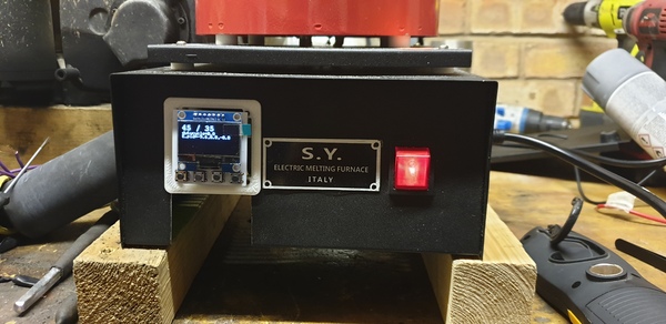
And finally I made a case to house the front panel PCB, which is screwed inside the plastic.
The button caps are connected to each other by thin strings of plastic to stop them from falling out, but the strings are thin enough to be flexible so that the buttons can all be operated independently. The writing, and the icons on the buttons, are printed in the same colour as the rest of the case, but raised up slightly, so that they can easily be coloured by rubbing across the top with a permanent marker.
The device is named by an obligatory series of inscrutable letters, and an impressively-large number, so that it can take its rightful place among the REX-C100s and CAL 9500s of the world.
So that's the story of my industrial process controller. It was a bit of a distraction from what I was meant to be doing (i.e. the actual task of sintering 3d printed metal parts), but it was fun and I learnt a lot. And if you happen to want to build one just like mine, I can offer free PCBs to up to 4 lucky readers!