
Since the last post I've been working on the hardware of my telescope. I think the hardware is basically done, I just have a bit more software to write, and then need to wait for a convenient and cloud-free night in which to try it out.
Parts
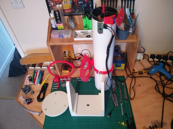
The tube has a 3d printed clamp near the centre of mass, with a bearing pressed into each side. It also has 120 degrees of a gear screwed to the side, for controlling the up-down angle ("altitude") of the telescope. At the top end I have fitted a large gear on the threaded rod that controls the focus, and a servo with a small gear that drives the large gear. The servo is able to turn through only 180 degrees, so most of the teeth on these gears are superfluous, but it gives plenty of range to manually adjust the focus without worrying about the gear alignment. Having got the focus in the right range manually, it can be fine-tuned using the servo. The focus is extremely sensitive, and I've found that the range afforded by the servo is about 10x more than is required.
You might think that the altitude motor could drive past the end of the gear, causing the tube to flip over uncontrolled or crash into the ground. This does not happen, because the centre of mass of the tube lies on the same side of the tube as the gear. This means if you drive off either end, the weight of the tube pulls the gear back towards the motor instead of flipping it over. This is both a blessing and a curse, as we'll see later.
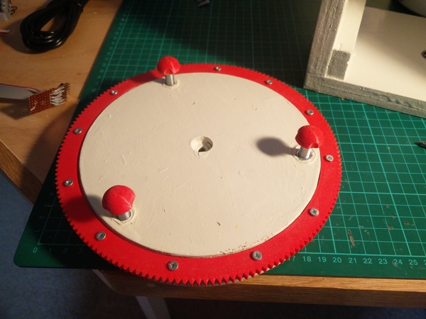
The base of the stand is a small circle of MDF. I cut this circle on the table saw using a technique I found on YouTube. I made a sled for the saw, and loosely screwed a piece of MDF to the sled. This allows us to take cuts that are a constant distance from the centre point of the MDF. By rotating the MDF around the screw slightly with each cut, we can cut off finer and finer pieces of corner, until what remains is indistinguishable from a circle. A great benefit of this technique (in this application, at least) is that we are left with a hole precisely in the centre, which can be used to align the hole for the pivot bolt. I cut a step into the circle using the same technique, with the blade lowered, and I 3d printed a ring gear to sit in the step. This gear will remain stationary relative to the ground, and the telescope will rotate by driving a gear around the outside of it. The gear is about as large as I can print in a single piece on my 3d printer.
I also pressed 3 nyloc nuts into the MDF, into which are threaded 3 bolts. These act as adjustable feet so that the telescope can be accurately levelled (without accurate levelling, the "altitude" axis would also contribute a bit of "azimuth" movement, and vice versa). I also 3d printed some finger-holds/rounded-feet and pressed them onto the heads of the bolts.
The teeth on these gears are only about 4mm tall. That means that if the centre point of the large gear is off the centre of rotation by only 2mm, it is impossible for it to mesh against the motor through a full 360 degree rotation. It would have been much easier (i.e. unnecessary) to centre the gear accurately if the entire base plate was 3d printed in one piece. I didn't want to do this as it would use up a lot of plastic, and it would be less rigid than a piece of MDF. A good compromise might be to add a bit of plastic in the centre of the gear that would locate around the bolt that serves as the pivot point (so that it would be impossible to install the gear off-centre) but still screw the entire thing to a piece of MDF for rigidity.
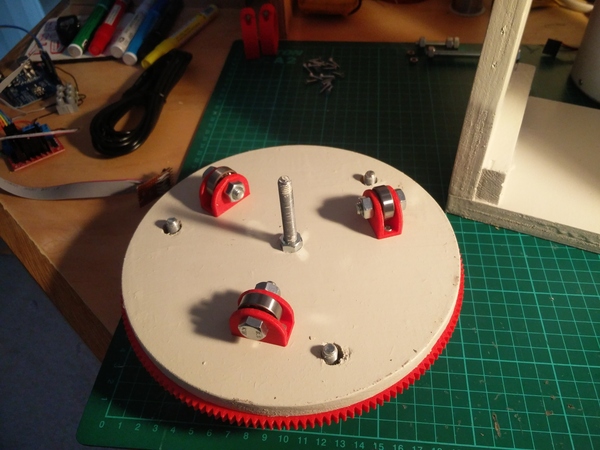
A bolt is installed through the centre of the base. This is the axis around which the top part of the stand rotates. I copied Patrick Aalto's idea of using 3 bearings in 3d printed holders as wheels to support the weight of the upper part.
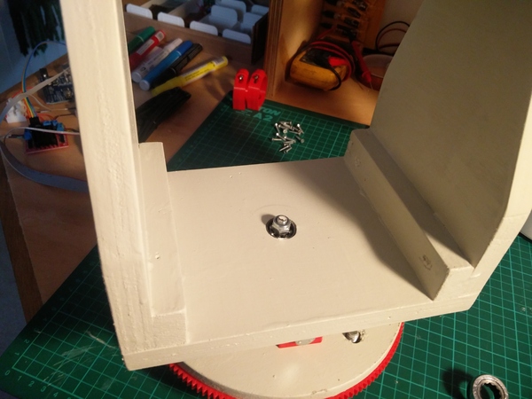
The upper part of the stand is made of plywood, glued and screwed together with wooden battens. There is a stepped hole in the middle with a bearing pressed into it to act as the rotation axis.
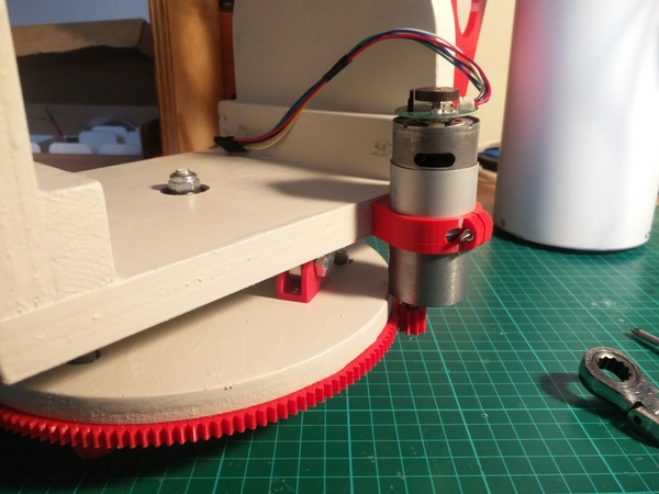
The motor for the left-right rotation ("azimuth") is held in a 3d printed clamp which is screwed to the side of the stand. Since the output shaft axis is offset slightly, the mesh of the gears can be adjusted by rotating the motor inside its clamp. And since the motor is roughly the same diameter all the way along, the alignment of the gears can be adjusted by sliding the motor up and down inside the clamp. I found the clamp to be a very elegant method of holding the motor.
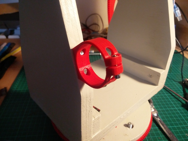
There's another identical clamp screwed to one of the uprights, for holding the altitude motor. The two holes at the top are to allow a screwdriver to be inserted to reach the screws that hold it in place.
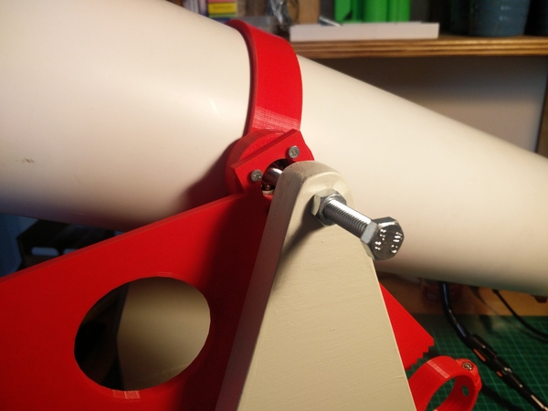
At the top of the stand we have a bolt in each side. These locate in the bearings in the clamp around the tube and are what hold the tube in place. From the first picture, the bolt on the right hand side is already in place. The tube is then lowered in and slid over the right hand bolt, after which the left hand bolt can be slid into its bearing, and then the nuts tightened around the plywood to hold everything in place:
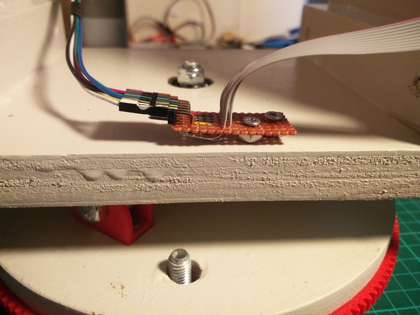
To connect the motor wires to the rest of the electronics, I soldered up a piece of protoboard to connect a ribbon cable to a 2-row right-angle pin header. Each motor has 6 wires (motor +, motor -, hall sensor 5v, hall sensor ground, hall signal A, hall signal B). I initially thought that the "Motor -" wires could both be connected to ground, but the L298N motor driver drives the motor in the reverse direction by applying positive voltage to the "Motor -" wire and ground to "Motor +", so they have to be unique to each motor. The hall sensor 5v and ground can be shared, however. So our 6 motor wires become "only" 10 wires on the ribbon cable. The wires in the ribbon cable are very thin, including the ones that supply power to the motors, but since the motors don't run for very long and aren't under much load, I think it'll be fine.
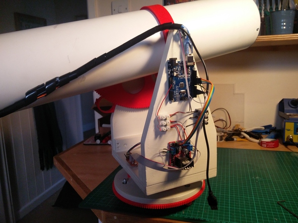
Finally we have the electronics mounted on the side of the telescope. The red circuit board at the bottom is the L298N motor driver. At the top is the Arduino Uno, and there are also some chocolate block connectors for power distribution.
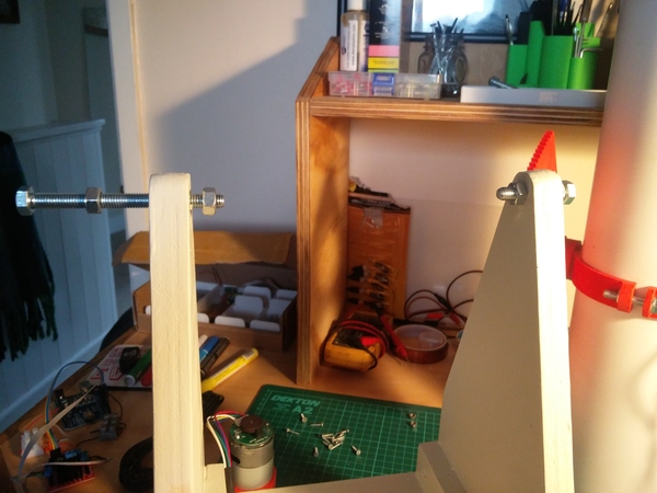
At the time I took these pictures I had only received one of the motors. The "altitude" motor is installed like so:
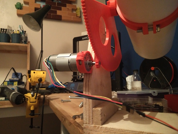
I don't like how it overhangs on the side, and it is designed so that it can be installed "inboard" and still leave the tube a full 90 degrees of altitude control without crashing into the motor, but it was more convenient to screw it to the piece of wood that was already there than to make a little wooden bracket to hold it. Maybe I'll move it in one day. Probably not.
I modelled all of the 3d printed parts except the gears in FreeCAD, and I made the gears using a gear generator library in OpenSCAD.
Problems (and some solutions)
Step resolution
I wrote last time that the encoders on the motors gave 4096 steps per rotation of the output shaft, which should give us 0.08 degree increments in positioning if not geared down. Since learning how to read a quadrature encoder properly, I have learnt that there are actually 4x as many steps available, so after the 19:1 gear reduction, we can measure 0.02 / 19 = 0.001 degree increments. That's pretty good! The PiKon has a field-of-view of about 0.25 degrees, so we get 1/250 of the field-of-view per step.
Unfortunately it is almost impossible to actually turn the motors to an exact step count. 1 step is about 1/16 of a turn of the actual motor (i.e. the motor itself, before its little gearbox). I found that if you want the motor to turn for 10 steps, you need to switch it on for about 6 milliseconds, which means each step is 600 microseconds. But trying to do exactly 1 step sometimes results in no steps at all, and sometimes results in 2 or 3, simply based on how close the shaft is to the different low spots in the internal magnetic field, I guess? I eventually gave up on trying to hit exact step counts and just let it tolerate anything within 4 steps of the target, which brings us back up to what I thought the resolution was in the first place, so we can target about 1/60 of the field-of-view.
Using actual stepper motors would be the correct thing to do, instead of trying to make DC motors approximate steppers. If I were to do it again I would use stepper motors.
Wobbly image
I've tested the telescope so far by pointing it at far-away objects out my window, and I have found that the image gets quite wobbly while the motors are tracking objects in the sky. I am not completely sure why, but I think it is a combination of comparatively-high acceleration when the DC motors switch on and off, a lack of rigidity in the tube, and the rolling shutter of the camera.
Using stepper motors with smooth stepping (or ramping the current to DC motors up/down more gradually) would solve the acceleration problem, which would mean lack of rigidity wouldn't matter, but there is no way to get rid of the rolling shutter without replacing the camera (and therefore also the Raspberry Pi) with something considerably more expensive.
Object tracking
Being able to target 1/60 of the field-of-view would be fine if we just needed to aim at static objects. But the Earth is rotating, and when your field-of-view is only 0.25 degrees, objects near the horizon can move entirely from one side of the frame to the other in only about 2 minutes, which means targeting 1/60 of the field-of-view means the object moves from one "step" to the next in 2 seconds. The camera has a resolution of 2592 pixels across, so 1/60 is 43 pixels. That means any kind of long exposure will have quite a blurred image. Even a 0.5 second exposure could have 10 pixels of motion blur.
My "solution" to this, combined with the wobbliness of the image while moving, is to forget about trying to do mega-long exposures and rely on exposure stacking instead. We could aim the telescope so that the object is at the top left of the frame, pause the tracking to keep the telescope still, and take many short exposures until the object leaves the bottom right of the frame, and then re-aim so that the object is at the top left once more. Having collected a large number of short exposures, we can (manually) align them as pixel-perfectly as possible, and add the images together. In this way we could approximate a single, accurately-tracked, long exposure. It remains to be seen how well this will work.
A better solution would be to have finer control of the step count, and to fix the wobbling.
Backlash
Backlash is where a drive system has a "dead zone" when switching direction.

In the diagram, the lower gear is rotating anti-clockwise to drive the upper gear. If the lower gear were to stop and change direction, its first small movement would be taking up the backlash rather than driving the upper gear in the reverse direction. This is pretty unavoidable. If the backlash were completely eliminated, the gears would bind against each other instead of moving freely.
What this means is that when you move the motor 20 steps forwards and then 10 steps backwards, the output gear is not at exactly the same point as it would be if you drove it 10 steps forwards. The more backlash, the further away it will be. The easiest way to deal with this is to ensure that you always reach your step count from the same direction. If you are at position 20 and you need to reach position 10, just drive all the way back to position 5 and approach 10 from below, and you'll be at the right place. That's fine when you can get away with it, but is not really suitable for tracking objects with the telescope, because you won't track the object very well if you keep having to drive past it, then drive forwards every time it moves 1/60 of the field-of-view.
Backlash can be compensated numerically. If you know there are always about 3 steps of backlash, then you can make sure to move the motor 3 steps past the desired step count when turning in the reverse direction, and the problem is pretty much gone. This would work for the azimuth (left-right) gear.
(If you're interested in this sort of thing, you might enjoy This Old Tony's Build Your Own CNC series on YouTube, in which he covers using commercial software and electronics to build a CNC "Etch-a-Sketch".)
But this brings us back to the altitude (up-down) gear. Since the weight of the telescope is always pulling it towards the centre of the gear, the backlash direction actually inverts as you move it past the 45 degree point! That is more complicated to compensate in software, and it probably means there is a small range of positions that is quite difficult to reach because the telescope gear will essentially be "floating" in the space between the teeth on the motor gear. I'm planning to ignore this.
My GUI will have to have some buttons to calibrate the precise position of the telescope, since it has no sensors which would give it an absolute concept of which direction it is pointing. I plan to use this GUI to manually fine tune the aim when pointing at a new object, and then the backlash only needs to get taken up during the calibration, and then the object will be tracked accurately (modulo passing the midpoint of the altitude axis).
Power supply
I was initially planning to supply all of the power through the Raspberry Pi. I'd have a long USB cable powering the Pi, the Arduino would be powered via its USB connection to the Pi, and the motors would be powered via the Arduino. Unfortunately the current spikes when the motors start and stop are too much. They caused the voltage to drop for a split second, and the Pi kept resetting itself.
I've now settled on adding a second power supply via the barrel jack on the Arduino. It is safe for the Arduino to be powered simultaneously through the USB port and the barrel jack, because it has an opamp to make sure the Arduino is powered by at least one input, while isolating the two power sources from each other.
This means the motors are powered through the barrel jack, and the Pi is powered through its USB port, and the Pi does not suffer voltage drops when the motors come on or off. It does mean that the telescope must be powered with 2 cables, but that's fine. I have twisted together a 3 metre USB cable and a 3 metre car-socket-to-barrel-jack cable, so that I can power both cables from within a car when "on location".
Cabling
Most of the cables on the telescope are confined to the upper section of the stand, and therefore they all remain in the same place, relative to each other, as the telescope moves. The cables that need to go to the end of the tube are bundled up in some cable wrap, and routed very close to the centre of rotation of the tube, so that the length remains constant and the cables never have to stretch.
The power supply cables, however, are in danger of getting wrapped around the telescope, or tangled up in the gears, if the telescope rotates around and around itself. I plan to ignore this problem for the time being. Hopefully I won't do enough full rotations in any one sitting for it to become a problem, and if I do, hopefully I'll notice something is wrong and fix it before it causes any damage.
A fun solution to this would be to mount a large-ish Lithium battery on the telescope itself, so that all of the cabling is contained within the stand and nothing can get wrapped around it. But charging batteries is annoying so I'd rather not have to bother.
Software
I've written a lot of the software, but not all of it. It's in https://github.com/jes/pikontroll (but the repo is a mess). Currently there is a program for the Arduino that receives instructions over the serial port and controls the motors and focus servo accordingly. There is a program for the Raspberry Pi that receives equatorial coordinates over the network from Stellarium based on this example code, converts them to altazimuth coordinates using mostly Patrick's code, and then sends instructions to the Arduino over the serial port. This program can also receive instructions to adjust the calibration of the motors and set the servo position.
Patrick lamented that Stellarium only sends the equatorial coordinates once every time you tell it to, which means the telescope points at the point you tell it to, but then doesn't keep tracking it. But given that most celestial objects don't move very much relative to the background, and the conversion from equatorial coordinates to altazimuth coordinates only depends on the current time, it is quite easy to recompute the altazimuth coordinates periodically and keep the telescope tracking the last coordinates that Stellarium sent to it. This unfortunately won't work for tracking satellites, but it's good enough for planets, the moon, stars, etc.
There are still lots of bugs in my software, and I still need to write some sort of GUI, either integrated into RPi Cam Web Interface, or a separate web page that I'd open in a separate tab.
I was surprised with how much software has been required. As with most software, most of it is just "plumbing", i.e. connecting together different parts that need to interoperate on the same underlying reality.