
I've made a bit of progress on the CNC mini mill project, and have made some cuts, although currently it's still not in full working order.
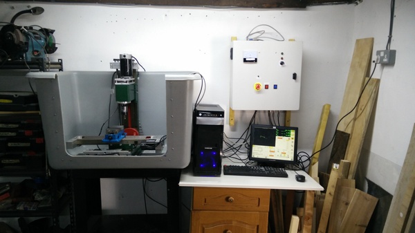
The machine is now installed in its tub, with the control cabinet on the wall and the PC on a little desk.
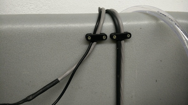
I've also restrained the cables with a handful of little 3d-printed clips, so that they can't get snagged:
Motor
I've wired up the spindle motor with an analogue ammeter for a crude "spindle load" display:
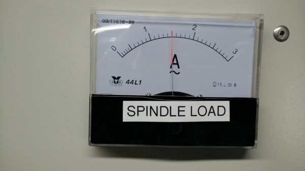
I found the spindle load display very useful for "manual" drilling, in the absence of a manual quill. I can modulate the Z feed rate using the jog pendant (see below) while watching the spindle load, to maintain cutting load without overloading the motor. It's also helpful generally for knowing how close a cut is to the limit of the motor. It seems to be fine with anything below 2 amps, but starts to stall if it exceeds 2 amps for more than a few seconds.
I've fitted one of those magnetic tachometer kits so that I can get a spindle speed display:

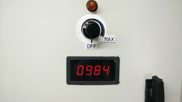
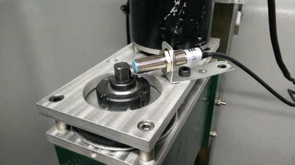
For the time being I've just stuck the magnet to the drawbar magnetically. It hasn't flown off and hit me in the face yet.
PC
I bought and installed the cheapest non-Nvidia GPU I could find on eBay, and it has solved the problem where OpenGL usage on the integrated GPU would crash the machine. That means I now have access to a much wider range of LinuxCNC screens, and I'm now on Gmoccapy instead of Qtaxis.
Surprisingly, the LinuxCNC screens seem a lot less mature than UGS Platform does. They all have weird bugs and strange UX. In Gmoccapy:
- If you edit a G-code program, save it, and then try to return to the main GUI, it asks you if you're sure you want to exit with unsaved changes. Even though you just saved. The problem is that there are too many abstraction layers and the save button has no way to communicate the fact that the text has been saved, either to the textbox or to the GUI.
- I have to manually click "home all" to unlock some parts of the GUI even though homing is a no-op on my machine.
- "Restart from line" does not reset to 0 after restarting. "Restart from line" is a useful feature that allows you to restart an aborted program from a line that you deem sensible, without having to manually delete all of the lines that come first. The problem is that a.) once you have restarted a program from a given line, any time you start a program, it will always start from the line number you last entered, even if the program completely finished and you've opened an entirely new one where carrying over the line number makes no sense, and b.) the starting line number is not displayed anywhere, so you just have to remember to manually reset it to 0.
- There is no cycle time estimate. UGS Platform has a really simple cycle time estimate based on the assumption that every line of G-code takes the same amount of time to execute. This is fine and useful enough, but Gmoccapy just has nothing.
I looked at fixing some of this, but the code running on my PC seems to be significantly different to the code on github, so I guess improvements are being made, and my problem is just that the latest release is quite old.
Probe_basic looks to be a really nice GUI for LinuxCNC, and even has a "conversational" interface where you can for example ask it to do simple facing operations without having to create a G-code program yourself. Unfortunately it requires a display of exactly 1920x1080 pixels. The display I'm using is only 1024x768 so it doesn't fit. I tried a (very bad) spare 1920x1200 display that I have, but Probe_basic seemed to scale itself to fit the 1200 pixel axis instead of the 1920 pixel one, so some of the horizontal space was hanging off the edge of the screen. I gave up in the end and reverted to Gmoccapy and the 1024x768 screen.
Jog pendant
Before starting a program, you need to set the coordinate system so that you machine material out of your work piece, instead of the air or the vice. This involves manually "jogging" the tool around to find a reference position and then setting the coordinate system from there. Unfortunately my computer is the other side of an opaque laundry basket, so when I can reach the keyboard I can't see where the tool is.
For this reason I have made a "jog pendant" that I can hold while standing closer to the machine.
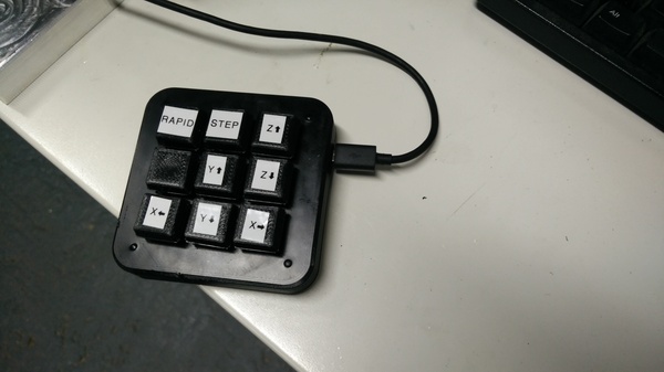
It is just a 9-key macro keypad, inside a 3d-printed case. Pressing "Step" sends an "i" keypress which is what Gmoccapy uses to change the step size. Pressing "X left" sends a left arrow keypress, which moves in the negative X direction, and so on. "Rapid" is a shift key. Holding shift makes Gmoccapy jog at full rapid speed instead of the configured jog speed.
Making chips
After I first got the motor wired up, I clamped down a piece of aluminium and ran an end mill back and forth just to get a feel for it.
(I knew the workholding was poor, I just didn't have anything better available.)
I was not very impressed with the power of the motor! It kept stalling on relatively shallow cuts in a relatively soft material. At first I thought I was definitely going to have to get a better motor, but I think my main problems in that video were that the drawbar was loose (you can hear it rattling), the workholding was inadequate, the spindle speed was too low, and the cutting tool was blunt. It works a lot better now that I've fixed those problems.
The first actual G-code I ran was to make some shapes out of a piece of aluminium:
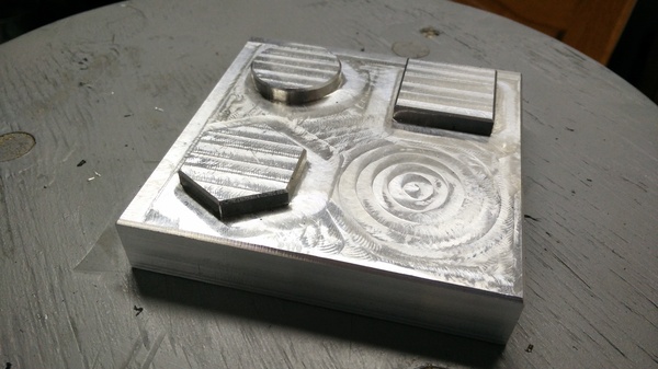
You can see there are some ridges in it. These are partly caused by loose Z-axis gibs, and partly caused by the head being out of tram (i.e. not perpendicular to the table in every direction). I have since tightened the gibs but still need to work on tramming.
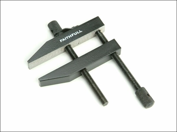
For my next trick I thought it might be fun to create a toolmaker's clamp, like this:
I didn't have a suitable piece of square steel, so I used round bar instead. This is not a bad thing as it gives me good practice at using the machine to create the shapes I desire. I made this:
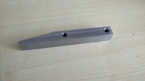
The surface finish is OK, and I'm really pleased that I can now machine steel parts. But there are a number of notable problems here. There is still a step in the top surface from the machine being out of tram. The finish on the sides is quite rough because my finishing cut chattered quite badly due (I think) to backlash in the X and Y axes. There were a few false starts while I was getting my toolpath sorted out which led to a few chunks taken out of the end:
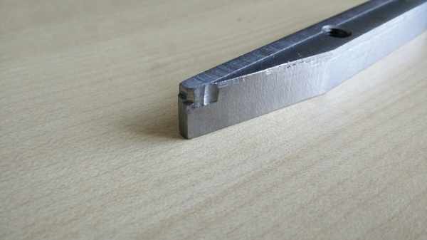
But mainly I am foolish and drilled the holes in the wrong axis! So this is now completely useless. Oh well. I'll have another go once I've sorted out the backlash and got the machine back together.
The holes are also not centred properly. This is because I had the steel sitting on parallels in the vice, and I wanted to avoid drilling into the parallels, so I drilled the holes by hand. This seems like a problem I'm likely to encounter a lot, so I need to come up with a solution eventually. Maybe I'd just drill the holes most of the way through on the milling machine, and then finish them up by hand?
Halfway through making this part my nice new sharp end mills arrived, and they are a big improvement. I can see on the spindle load meter that the load for the same cut is much lower, which also implies I can take heavier cuts, and the surface finish is visibly better on the parts that were cut with the new end mill.
Backlash
I found that the Y axis backlash was caused by the screws holding the ballnut to the carriage being loose. They are only phillips head screws which I can't tighten satisfactorily, so I have replaced them with allen bolts now. I had to order the bolts, but the delivery crossed the Jubilee weekend so the wait was annoyingly long. It was tempting to reinstall it with the original screws, but I know I'd have to take it apart again and getting it this far apart is a lot of work so I'd rather not have to do it again. But anyway I think that problem should be solved now.
There was also a small amount of X axis backlash. I found that there were plastic spacers in between the ballnut and the holes that it seemingly bolts on to. Originally I was just going to throw the plastic spacers away, but when I came to reinstall the ballnut I found that the holes don't line up. I also found that the screws holding the ballnut on were M5 while the holes are only M4! How did this work??
Some head-scratching later, I realised that the bolts were only threading into the plastic "spacers" and pushing against the surface with the M4 holes, to push the ballnut against an opposing surface, and this is how the ballnut was attached. What a bodge! This is what happens if you buy unfinished projects on eBay.
Ideally I would drill new holes near the M4 holes and tap them to M5, but unfortunately the required hole location overlaps the existing holes so it would be very difficult to drill and tap. I also looked at widening the holes in the ballnut so that I could get M4 screws to line up with the M4 holes, but the ballnut seems to be made of incredibly hard steel and it blunted both of the drill bits that I tried to use.
So my current plan is to replace the 2 plastic spacers with an aluminium one that spans both holes. With an aluminium spacer I will be able to do it up tighter and hopefully it won't come loose. Again these screws had phillips heads so I want to replace them with allen bolts, but I didn't have any long enough in M5 so I'm again stuck on waiting for delivery of bolts.
Flood coolant
I have made a bit of progress on getting flood coolant set up. The main impetus for this is that I was previously manually dripping oil onto the steel, and this makes very oily and sticky chips that are difficult to clean up.
I bought "Sabre Sol 2B" on eBay. I chose this coolant because it is available in 1 litre bottles. Most water soluble coolants seem to come in enormous quantities. The instructions say to dilute it with water somewhere from 5% to 10% depending on whether you're milling or drilling. Since I'm doing both I just guessed at a concentration somewhere in between.
My main concerns with the coolant are whether it will rust the precision surfaces on the machine, and whether it will short out any electronics it comes into contact with. I stuck my multimeter probes in it (on the 2 Megaohm setting) and didn't manage to measure any conductivity at all unless the probes were touching each other. So I guess it's non-conductive enough? I will not deliberately submerge my connectors in it, but I think getting it splashed on them won't be a problem.
I had some drops of coolant sitting on the machine overnight and they seem to have evaporated without leaving any rust behind, so that's looking like a winner too. I expect it's designed not to cause rust, but it feels very odd to deliberately spray 90% water onto steel surfaces that you care about.
Here's a video showing my coolant system as it stands at the moment:
The big problem is that it pumps much faster than it drains, so if it were running continuously it would flood the tub and run the pump dry. So I need a bigger drain hole.
The pump I got was this one on Amazon. The Amazon listing says it can pump 2000 litres per hour and lift water 15 feet, but the markings on the pump only say 1.5 metres. Either way it seems more than adequate for my use case.
Fly cutter
Once I've successfully made a toolmaker's clamp, I think my next milling project will be a fly cutter.
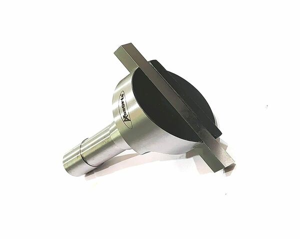
This is basically like a lathe tool, except it mounts in the spindle of the milling machine and spins around. The cutting point scribes a much larger radius than a normal end mill, and it is supposed to give a superior surface finish compared to machining lots of parallel lines with a normal end mill.
The first thing I would do with the fly cutter is re-cut the top surface of my vice jaws to fix a previous blunder...