
A laser level is a device that projects a laser beam on to a wall or similar, to help you position things level to the ground.
I have never actually seen or used one, but a DuckDuckGo image search gives lots of examples. This picture pretty much illustrates the concept:
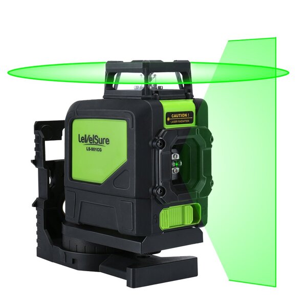
(Although, for the purpose of this post, I'm only interested in the horizontal beam and not the vertical one - but a vertical beam could be implemented exactly the same way).
Basic design
I first started thinking about laser levels a while ago when Jez got one and explained to me how great it was. Yesterday I came back to them after watching AlphaPhoenix's video on why smoke from a soldering iron always goes towards your face, in which he builds a device that projects a laser beam to illuminate a cross-section of smoke in air. In principle it is actually quite easy: you just need to mount a mirror on a motor at 45° and spin it really fast, and then point a laser at the mirror. As the mirror spins, the laser beam is projected in different directions around in a circle, sweeping out a plane in space. If you can make sure the plane is level to the ground, then you have a functional laser level.
You could mount the laser directly on the shaft of the motor and not even need a mirror, but then you need to supply power to the laser using slip rings, induction, batteries, or something else. Seems easier to just use a mirror.
The idealised solution looks like this:
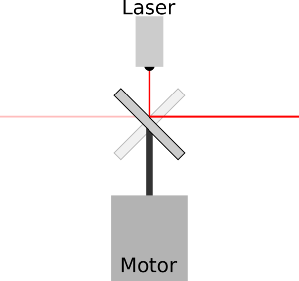
(I drew it in Inkscape).
The motor is mounted perfectly vertically, the laser beam is co-axial with the motor, and the mirror is at a perfect 45°. As the motor (and therefore the mirror) rotates, the laser beam sweeps out a horizontal plane parallel to the ground.
I got to thinking about how to actually build one in practice, which led to some observations about how the laser beam could sweep through a path that is not a horizontal plane parallel to the ground.
Sources of misalignment
Without loss of generality, we'll treat the motor shaft as our reference axis, and assume that it always points vertically up.
It is possible for more than one of the following misalignments to be present at any given time (and in fact, in real life, they are all always present to some extent), but it's relatively straightforward to imagine how they combine so I have not explicitly shown this.
Mirror angle
If there is some misalignment of the mirror, then instead of a plane, the laser beam sweeps out a cone in space:
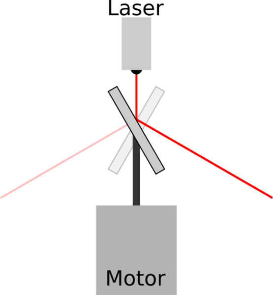
If the mirror is θ° away from the correct 45°, then the cone of light drops (or rises) away from the intended horizontal plane by ½θ°.
This is a problem, because if we're sweeping out a cone then points are illuminated at a different height above the ground depending on how far away from the laser they are. Not very useful. A flat wall would be illuminated as a conic section, which would be a hyperbola in the likely case, but possibly a parabola or even an ellipse if either the device or wall is extremely far out of level!
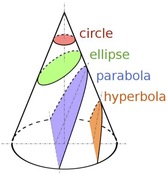
(Picture from Wikipedia).
The cone shown here is the cone of light from the laser, and the intersections of the flat coloured shapes with the cone represent the path that would be traced out on a flat wall at different angles relative to the cone: the hyperbola is if the wall is steeper than the sides of the cone, the parabola is if the cone's sides are parallel to the wall, the ellipse is if the cone's sides are steeper than the wall, and finally the circle is achieved if the cone's axis is perpendicular to the wall surface.
Laser axis
If the laser is square to, but not co-axial with, the motor then the height of the illuminated point varies with the rotation angle.
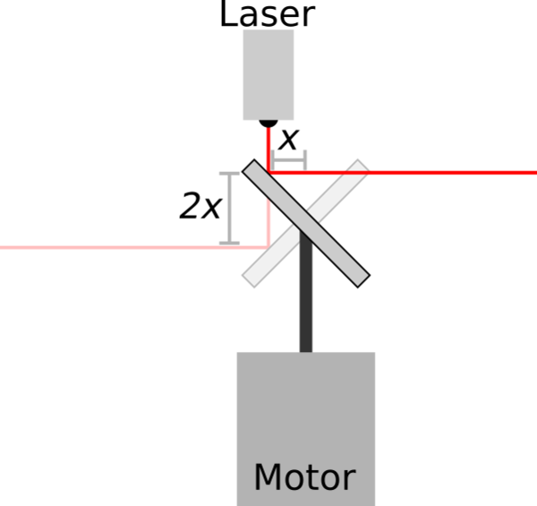
If the laser is off-axis by x mm, then the line height varies by 2x mm through its rotation (i.e. ±x mm from the centre line). I assume it is a sine wave but have not proved it.
This is actually not that bad. It's quite reasonable to be able to align the laser within a few millimetres of the motor shaft, even if the parts are made by hand. And unlike with angular misalignment, axial misalignment does not get worse as the projected point gets further away (in fact, it gets better, because if you're further away then points that are a given distance apart on the wall are relatively closer together in terms of rotation angle). It is unlikely that this misalignment would result in a laser level that is not usable, but for particularly high-precision applications it might be something to consider.
Laser angle
I initially thought that if the laser were not square to the motor, this would give a cone as well, but as I was drawing the diagram I realised that as long as the beam intersects the mirror at exactly the centre of rotation, then it would actually give a plane, just not level:
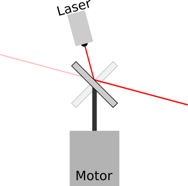
If the laser is θ° away from vertical, then the horizontal plane is tilted θ° away from horizontal.
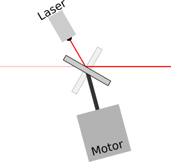
Interestingly, because this misalignment still results in the laser sweeping through a perfect plane, we could rotate the entire apparatus, even though the laser is not aligned with the motor, and still get a perfectly functioning laser level:
If I end up making one of these, then I would be tempted to tilt everything like this on purpose just for the extra challenge, because it's funny & surprising that it can still work. You just need to make sure that the laser beam intersects the mirror exactly at the centre of rotation, which could be achieved by allowing for some adjustment in the vertical position of the motor.
Positioning
Once we've achieved a motor-mirror-laser system that is all nicely aligned, then we need to be able to reliably position the device at a height of our choice, and make sure the base is level.
To position it at a given height, you could put a 1/4-20 UNC female thread on the bottom and mount it on a camera tripod.
To get it level, you could put a circular "bull's eye" spirit level on it and three adjustable feet, and manually level it each time you want to use it. This is what I did with my telescope and it works but is annoying.
Fancy laser levels (including Jez's) are able to automatically level themselves as long as they are positioned within a few degrees of vertical. I have thought of a couple of ways to achieve this.
Gravity
You could suspend the laser level from a short length of string, or a ball-and-socket joint, and let its weight pull it square like a plumb bob. This would work as long as the centre of mass is perfectly in the centre (but that's easy to adjust). The potential problem is that the motor might induce resonant vibration, which could result in a wobbly line, which would be more or less amusing depending on how badly you want a straight line on the wall.
You could overcome the vibration either with some damping, or by using a locking ball-and-socket. With the locking ball-and-socket you could just require the user to set the device up in place, wait for it to settle, and then tighten the joint so that it can't move before switching the laser on. It might be easy enough, but I would be concerned about the ball getting moved slightly as the joint is tightened up, and it does mean you have to commit to the height before you have even seen what the height is, so might actually involve multiple rounds of setting the height and then checking it.
2 servos and an accelerometer
This is a rather "brute-force" solution to the problem: a 3-axis accelerometer can detect when it is not level (because it'll have some X or Y acceleration), and then we can use 2 servos to level it in the XY plane. This would not be hard to implement, but it means adding a microcontroller to what would otherwise be a relatively mechanical project. Might be worth doing though.
Thanks for reading. I think that's all I have to say about laser level design for now.