
I wrote before about dismantling the control panel from my ebike to find out how it works, and had some ideas for an improved design.
Specifically, I wanted:
- Easily set the desired power setting when switching the system on, without having to wait or do multiple button presses
- Continuously-variable power setting, instead of just 3 modes
- Fine-grained battery meter, instead of just 4 LEDs
- Change the power level without looking at the display
And I had some plans involving an Arduino Nano and a 160x128 LCD display.
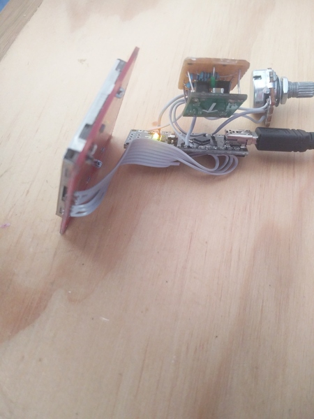
I wrote most of the code while waiting for parts to arrive, then assembled it on a breadboard and took it outside to test on the bike.
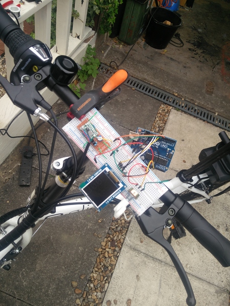
To my dismay, the display was practically invisible! The backlight is switched on, and adjusted optimally. That's just as bright as it gets in direct sunlight.
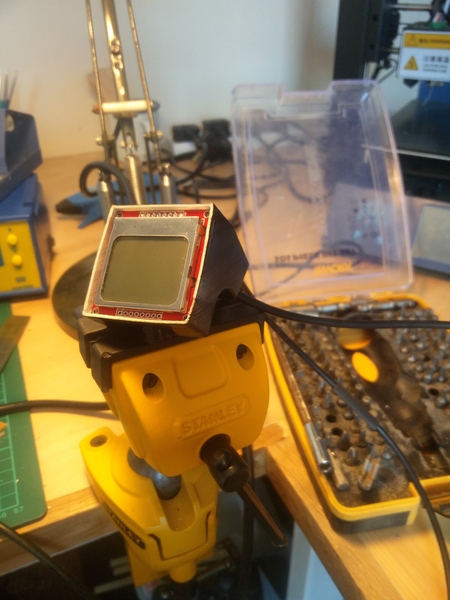
The display I ended up settling on is an 84x48 Nokia 5110 LCD. It is very clearly visible even in direct sunlight, so I rewrote the Arduino code to work with the Nokia LCD, modelled an enclosure in FreeCAD to mount the electronics on the handlebar, 3D printed it, sanded it, primered it (I used a filler primer, and lots of intermediate sanding steps), and painted it. I epoxied a thin piece of acrylic glass into the front, and assembled it all on the bike.
CAD model:

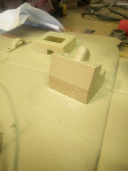
After printing, sanding, and primer:
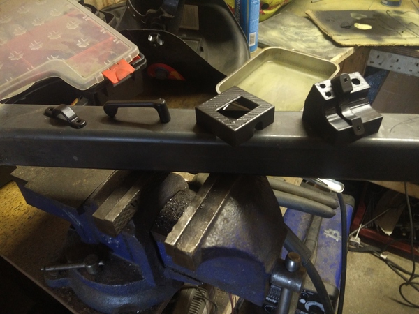
Painted:
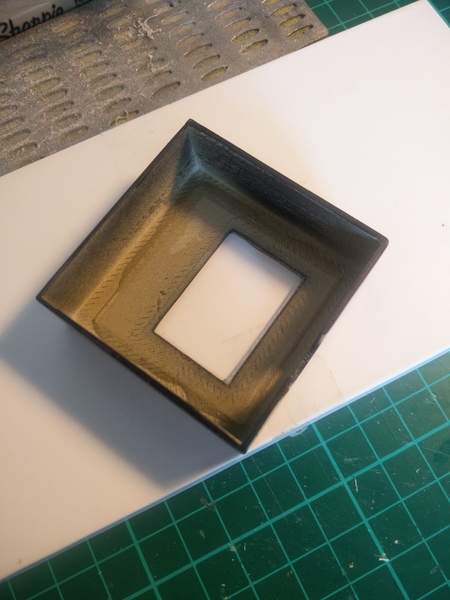
Gluing in the acrylic glass:
Some more pictures:

(The top and bottom halves of the enclosure just slide together and can be prised apart by hand; the tape inside is just to avoid any accidental shorts between the circuit boards.)
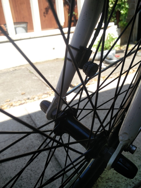
I am quite happy with the magnet pickup, and the handlebar clamp, and the finishing technique (while time-consuming) produces a good result. But the actual design of the enclosure is very boxy and obviously homemade, which is not what I wanted. And unfortunately if the edges were more rounded it would be even larger than it already is as it's built down to the dimensions of the circuit board the LCD is mounted on.
With my fancy new ebike control panel, I set off for my first proper test ride. In hindsight I should have done this before spending all of that time and effort on building and painting the enclosure. I discovered that my continuously-variable "throttle" input did not result in a continuously-variable pedal assist setting. It turns out the motor controller only supports 3 distinct modes. Disaster!
I put up with it for a little while, and even had an opportunity to test it in the rain, which worked fine (never doubted it!):
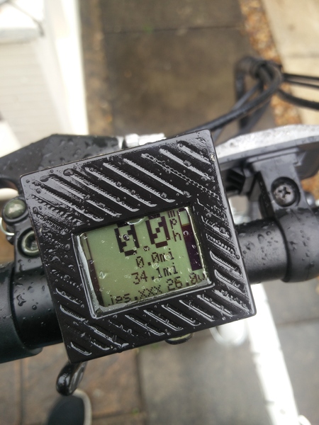
But with only 3 distinct modes, and a smooth lever as the input, it's impossible to know when you're going to move from one mode to the next. I modified the software so that the throttle lever indicator on the screen steps between 3 levels so you can at least tell which mode you're in by looking at the screen, but this is not much improvement on the system the bike had before.
It was around this time that I read Unquantified, which is about reducing the amount of data in your life, and just being content with not knowing. It's good.
This convinced me that I didn't actually need the speedometer or the odometer, and at that point the only thing the display is good for is the battery level, and maybe we could do without that as well. After all, if the battery runs out, it's not the end of the world. An ebike with a flat battery just becomes an ordinary bike!
So I designed a much simpler, purely analogue, control scheme. I bought a "3 pole 4 throw" rotary switch off eBay. A "2 pole 4 throw" switch would do, but is harder to find, or even a "1 pole 3 throw" if you're content with having a separate power switch. I wired it up so that in one position the "K" wire is disconnected from "VCC", and in the other 3 positions "K" is connected to "VCC", and "TUO" is connected to a point in a voltage divider made of 3 5K resistors and a 10K resistor. That gives a 1v drop across each of the 5K resistors, which gives us the 2v, 3v, and 4v levels needed to select the different pedal assist modes. Here's a schematic to explain what I mean:
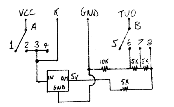
"A" and "B" are the common terminals of the rotary switch, with "1" to "8" being the corresponding switched terminals.
I used an LM7805 linear regulator to drop the battery voltage to 5v. For a higher-current circuit this would be an unreasonable voltage drop and would both waste power and cause the LM7805 to get really hot, but since this is essentially just a 25 KOhm resistor, it hardly draws any current.
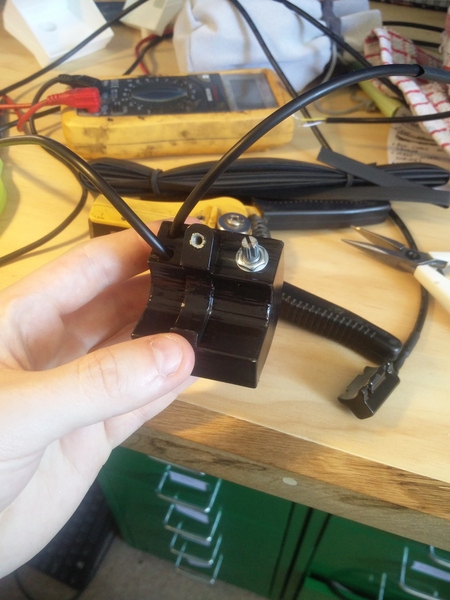
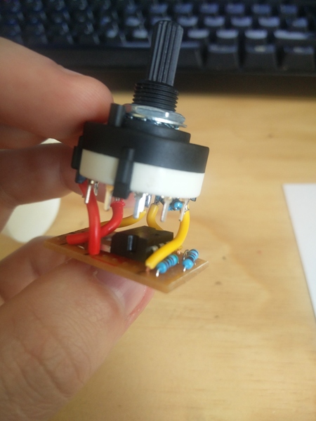
This was simple to make on a small piece of stripboard:
and this time I went with a simpler enclosure before wasting time on painting:
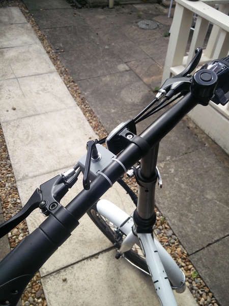
I've only ridden it a couple of times with this new switch, but am happy with it so far. I'd like to make a more elegant control knob (the knob on it at the moment is just the thumb lever from my first attempt at a control panel), and a neater enclosure, with labelled knob positions and a proper handlebar clamp, but it's pretty much there.
So how well did I meet my initial goals?
- Easily set the desired power setting when switching the system on, without having to wait or do multiple button presses: Success
- Continuously-variable power setting, instead of just 3 modes: Impossible without replacing the motor controller.
- Fine-grained battery meter, instead of just 4 LEDs: There's no longer any battery meter at all.
- Change the power level without looking at the display: Success.
I suppose 2 out of 4 ain't bad.